Rolling bearing apparatus
a technology of rolling bearings and rollers, which is applied in the direction of mechanical equipment, shafts and bearings, engine components, etc., can solve the problems of bearings not being properly lubricated and lubricant cannot be supplied to the interior of bearings, so as to prevent the insufficient lubrication of the guide surface of rolling elements and reduce the running torque remarkably
- Summary
- Abstract
- Description
- Claims
- Application Information
AI Technical Summary
Benefits of technology
Problems solved by technology
Method used
Image
Examples
first embodiment
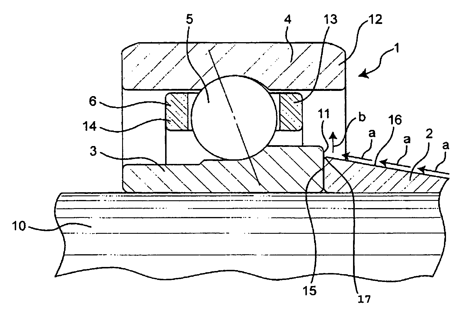
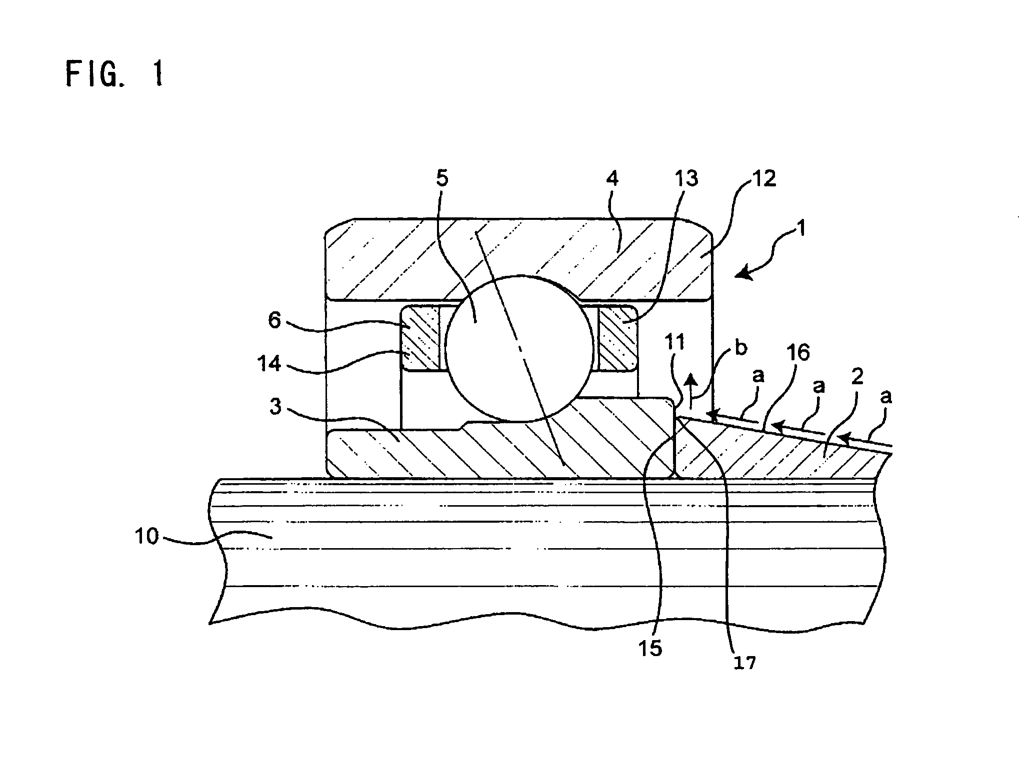
[0026]FIG. 1 is an axial cross-sectional view of a rolling bearing apparatus according to a first embodiment of the invention.
[0027]This rolling bearing apparatus is mounted in a turbo-molecular pump. The rolling bearing apparatus comprises a single row angular contact bearing 1 (which is one example of rolling bearings), and an inner ring contact member 2.
[0028]The angular contact ball bearing 1 is disposed between a rotation shaft 10 of the turbo-molecular pump and a housing (not shown). The angular contact ball bearing 1 comprises an inner ring 3, an outer ring 4, balls 5, and a cage 6. The inner ring 3 is fitted on an outer peripheral surface of the rotation shaft 10 extending generally in a vertical direction, and is fixed thereto. On the other hand, the outer ring 4 is fitted in an inner peripheral surface of the housing to be fixed thereto. The outer ring 4 has an outer portion 12 disposed axially outwardly of one axial end surface 11 of the inner ring 3. The plurality of bal...
second embodiment
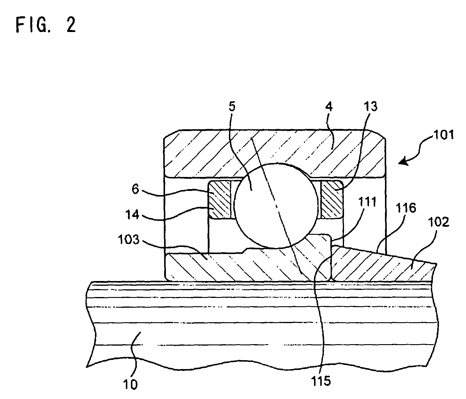
[0036]FIG. 2 is an axial cross-sectional view of a rolling bearing apparatus according to a second embodiment of the invention.
[0037]The rolling bearing apparatus according to the second embodiment differs from the rolling bearing apparatus according to the first embodiment in that an inner ring 103 has a shorter axial length and that one axial end surface 111 of the inner ring 103 disposed close to a conical outer peripheral surface 116 is disposed so as to overlap with a first annular portion 13 of a cage 6 (which is close to the conical outer peripheral surface 116) in a radial direction.
[0038]In the rolling bearing apparatus according to the second embodiment, those constituent portions identical to those of the rolling bearing apparatus according to the first embodiment will be designated by identical reference numerals, respectively, and description thereof will be omitted. Also, with respect to the rolling bearing apparatus according to the second embodiment, description of t...
third embodiment
[0043]FIG. 3 is an axial cross-sectional view of a rolling bearing apparatus according to a third embodiment of the invention.
[0044]The rolling bearing apparatus according to the third embodiment differs from the rolling bearing apparatus according to the second embodiment in that an inner peripheral surface 230 of a first annular portion 213 (which is a conical surface-side portion) of a cage 206 is gradually increasing in diameter in an axial direction toward balls 5.
[0045]In the rolling bearing apparatus according to the third embodiment, those constituent portions identical to those of the rolling bearing apparatus according to the second embodiment will be designated by identical reference numerals, respectively, and description thereof will be omitted. Also, with respect to the rolling bearing apparatus according to the third embodiment, description of the same operational effects and modified examples as those of the rolling bearing apparatuses according to the first and seco...
PUM
| Property | Measurement | Unit |
|---|---|---|
| outer diameter | aaaaa | aaaaa |
| outermost radius | aaaaa | aaaaa |
| radius | aaaaa | aaaaa |
Abstract
Description
Claims
Application Information
 - R&D Engineer
- R&D Manager
- IP Professional
- Industry Leading Data Capabilities
- Powerful AI technology
- Patent DNA Extraction
Browse by: Latest US Patents, China's latest patents, Technical Efficacy Thesaurus, Application Domain, Technology Topic, Popular Technical Reports.
© 2024 PatSnap. All rights reserved.Legal|Privacy policy|Modern Slavery Act Transparency Statement|Sitemap|About US| Contact US: help@patsnap.com


