
Switching power supply

a power supply and power supply technology, applied in the field of switching power supplies, can solve the problems of large variations in the overall drooping characteristic and the difficulty of obtaining a constant current drooping characteristic, and achieve the effects of low cost, sufficient accuracy, and constant current drooping

Inactive Publication Date: 2005-11-24
COLLABO INNOVATIONS INC
View PDF7 Cites 27 Cited by
  • Summary
  • Abstract
  • Description
  • Claims
  • Application Information

AI Technical Summary

Benefits of technology

[0009] In view of this problem, it is an object of the present invention to provide a switching power supply which can eliminate a constant current control circuit, a photocoupler, and an output current detecting resistor, eliminate the influence of variations in oscillation frequency and variations in the inductance of a transformer on a drooping characteristic, and achieve a constant current drooping characteristic of sufficient accuracy with low cost and the minimum number of components.

Problems solved by technology

However, also in this conventional technique, variations in oscillation frequency and variations in the inductance of a transformer affect a drooping characteristic, resulting in extremely large variations in the overall drooping characteristic.
Thus, it is quite difficult to obtain a constant current drooping characteristic.

Method used


Image

  • Switching power supply
  • Switching power supply
  • Switching power supply

Examples


Embodiment Construction

[0040] Referring to the accompanying drawings, the following will specifically describe a switching power supply according to an embodiment of the present invention.

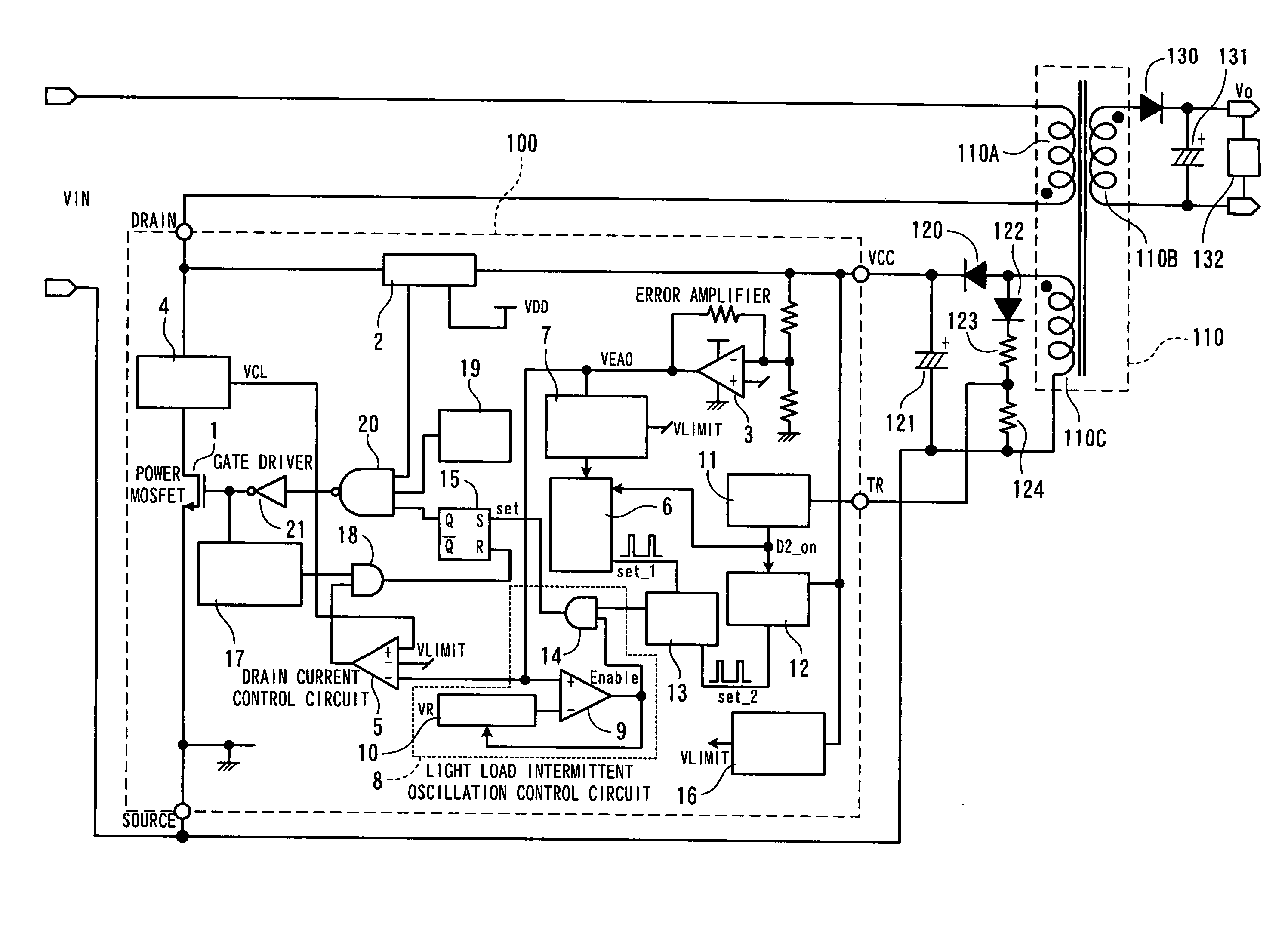
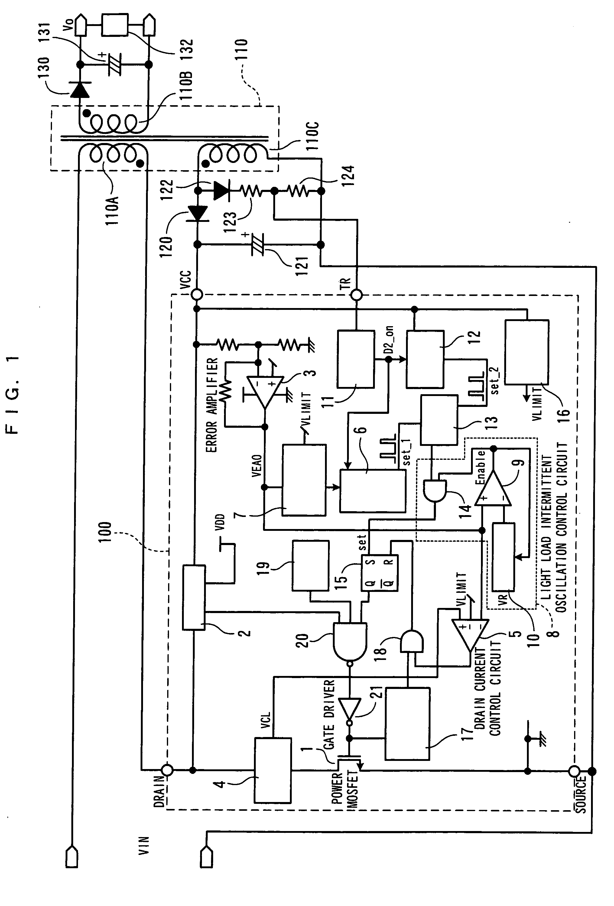
[0041]FIG. 1 is a block diagram showing a structural example of the switching power supply according to the present embodiment.

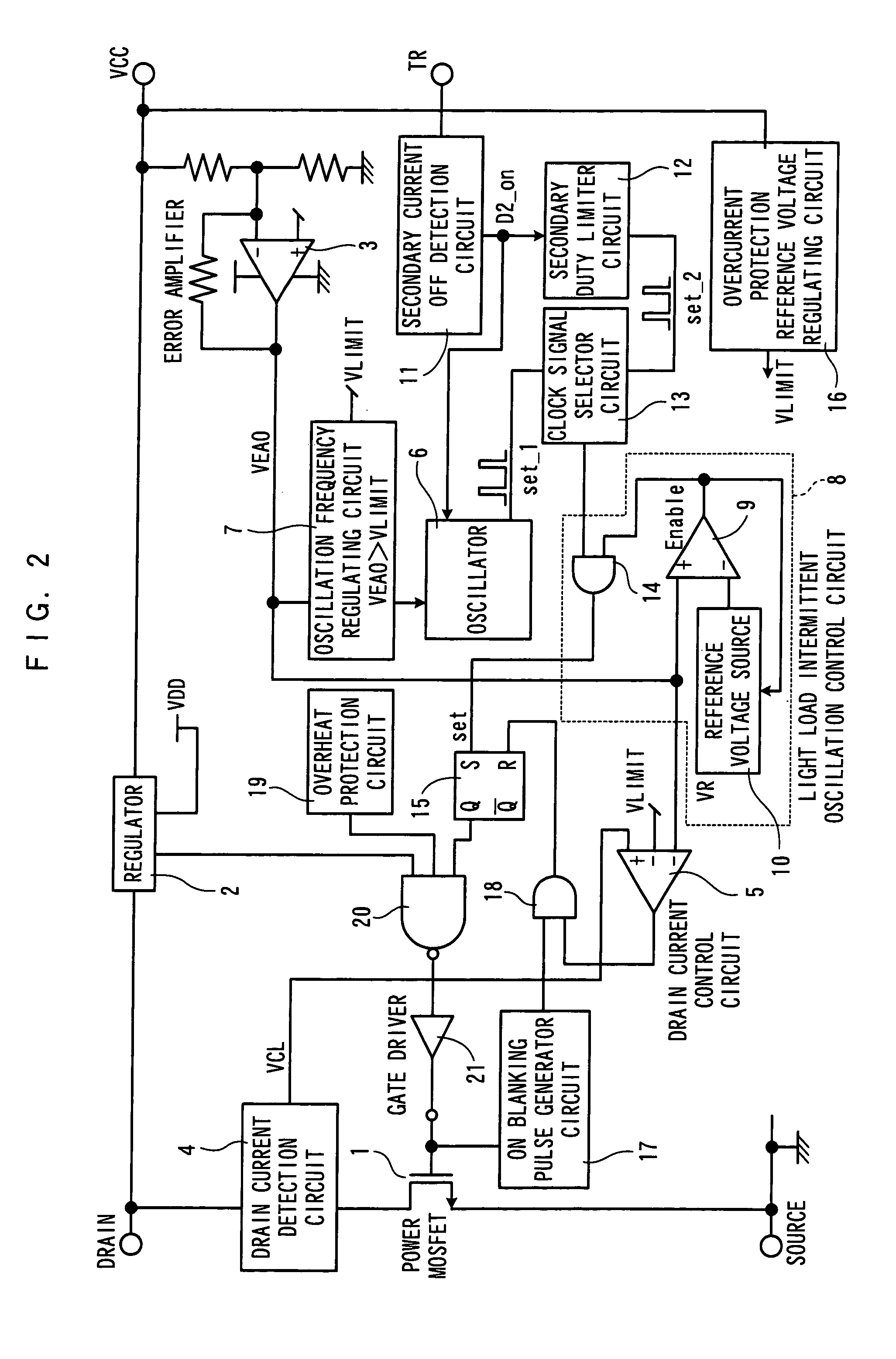
[0042] In FIG. 1, a semiconductor device 100 for controlling the switching power supply is constituted of a switching element 1 and a control circuit for controlling the switching operation of the switching element 1.

[0043] Further, the semiconductor device 100 comprises, as external input terminals, four terminals of an input terminal (DRAIN terminal) of the switching element 1, an auxiliary power supply voltage input terminal (VCC terminal), a secondary current off-timing detecting terminal (TR terminal), and a GND terminal (SOURCE terminal) of the control circuit. The GND terminal also serves as the output terminal of the switching element 1.

[0044] A transformer 110 has a primary winding 1...


PUM


Abstract

A switching power supply for achieving a constant current drooping characteristic of sufficient accuracy with low cost and the minimum number of components. In the switching power supply, a secondary duty limiter circuit outputs a clock signal from the time a switching element is turned off until the time the on duty of secondary current, which starts flowing to a secondary winding of a transformer, is fixed at a predetermined value. A clock signal selector circuit selects and outputs the clock signal when a load increases and the on duty of the secondary current reaches the predetermined value. Consequently, when the load increases, a direct current output voltage decreases and an output characteristic becomes a constant current drooping characteristic. At this point, when the voltage of an element current detection signal reaches an overcurrent protection reference voltage, a drain current control circuit outputs a turn-off signal for determining the turn-off of the switching element, therefore the peak current of the secondary current is kept at a fixed value.

Description

FIELD OF THE INVENTION [0001] The present invention relates to a switching power supply having a constant current drooping characteristic as an output characteristic. BACKGROUND OF THE INVENTION [0002] Conventionally, switching power supplies having a constant current drooping characteristic are used, for example, as power supplies for chargers. That is, the switching power supplies having a constant current drooping characteristic can charge batteries and so on by using the constant current drooping characteristic. [0003] For example, in order to obtain a constant current drooping characteristic in the conventional art, the secondary side of a switching power supply comprises an output current detecting resistor for detecting an output current, a constant current control circuit for controlling current passing through the output current detecting resistor at a constant value, and a photocoupler for transmitting the signal of the constant current control circuit to the primary side....

Claims


Application Information

Patent Timeline
Patent Type & Authority Applications(United States)
IPC IPC(8): H02M3/335H02M7/00
CPCH02M3/33507H02M1/32H02M3/28
Inventor MORI, YOSHIHIRO
Owner COLLABO INNOVATIONS INC
Learn More