Optical fiber hermetic termination connector
- Summary
- Abstract
- Description
- Claims
- Application Information
AI Technical Summary
Benefits of technology
Problems solved by technology
Method used
Image

Examples
Embodiment Construction
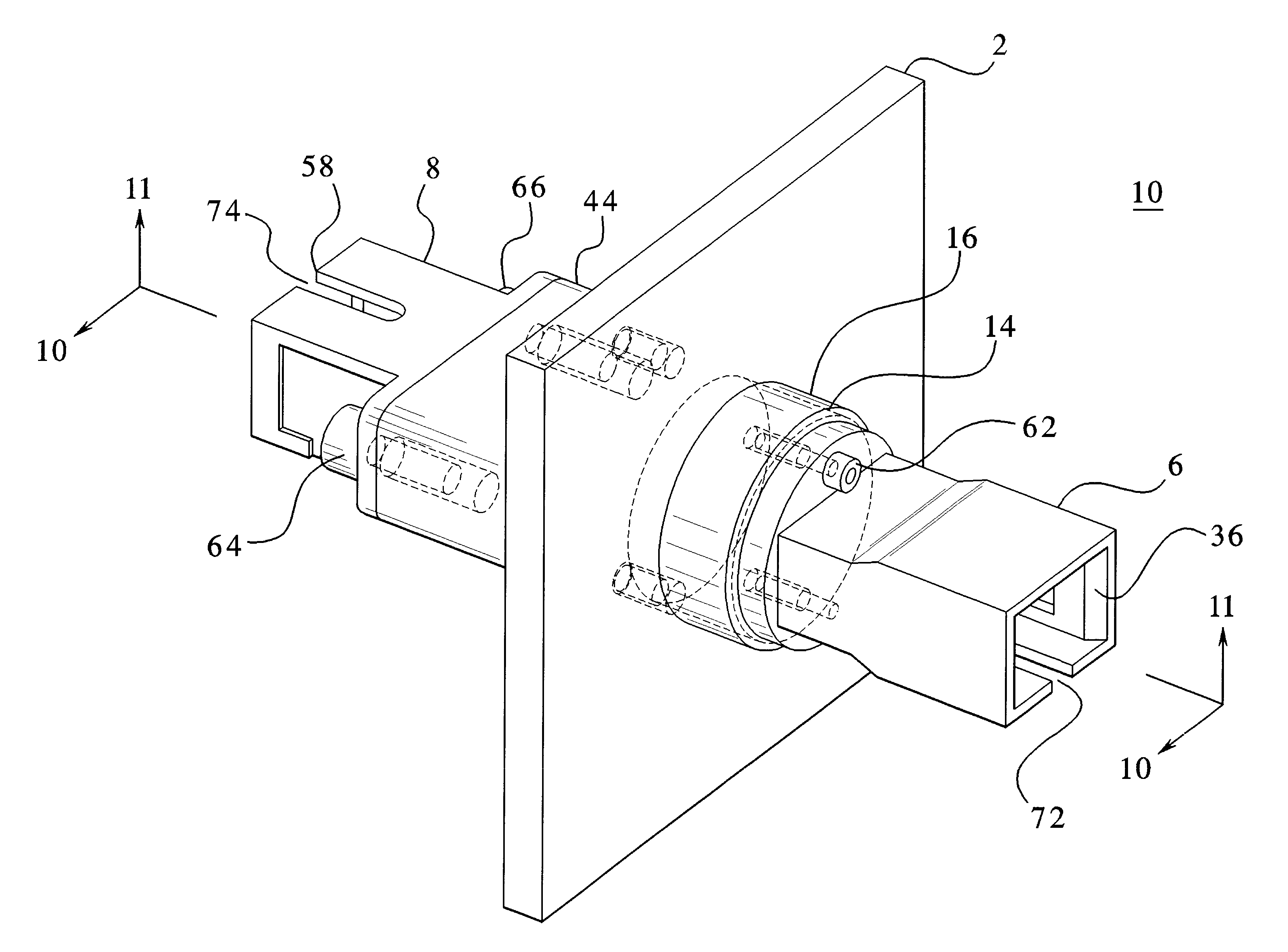
Referring now to the drawings, wherein like reference numerals designate identical or corresponding parts throughout the several views, and more particularly to FIGS. 1-11, an embodiment of the present invention is an optical fiber hermetic termination connector 10.
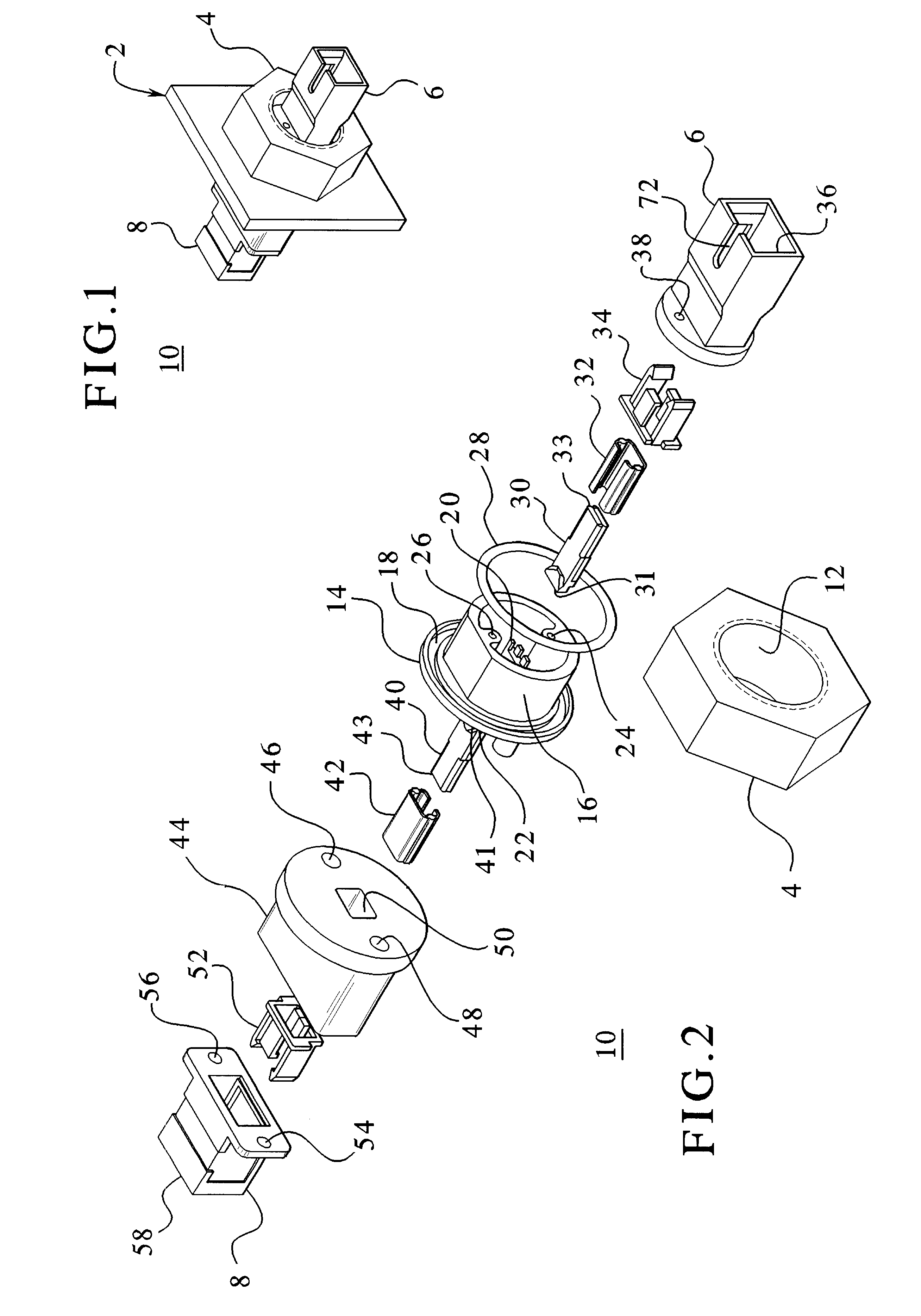
FIG. 1 is a perspective view of the hermetic connector 10 of the invention mounted to and through a wall 2 of a device. Also shown are a nut 4, a first coupling housing 6, and a second coupling housing 8. The wall 2 may belong to a device or chamber where atmospheric conditions exist on one side of the wall 2 and a vacuum exists on the other side of the wall 2. The connector 10 seals the opening in the wall 2 while allowing data to be transferred through the wall 2.
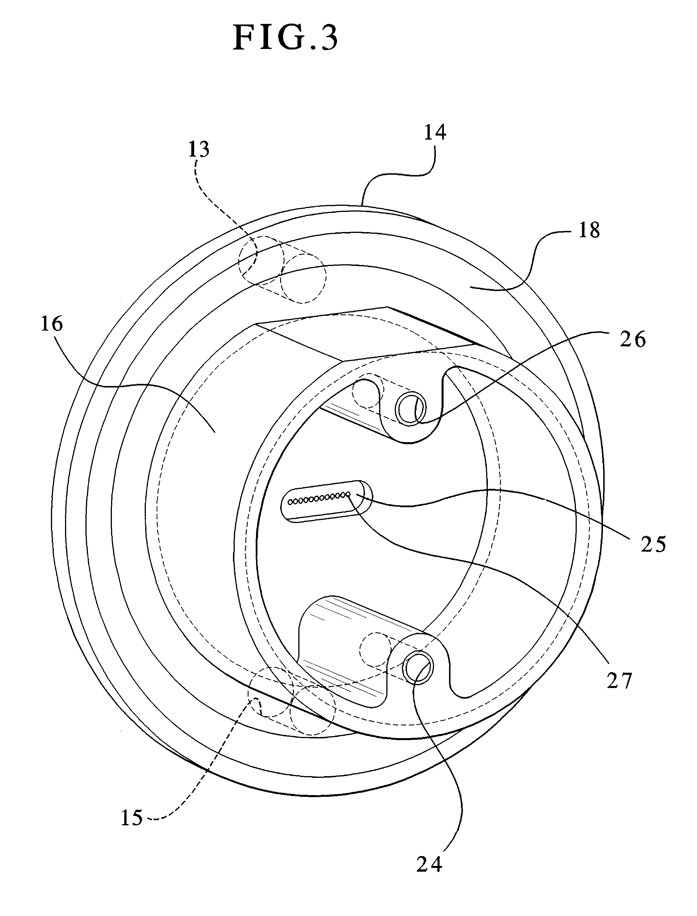
FIG. 2 is an exploded perspective view of the connector 10 with the wall 2 removed. A body 14 includes an O-ring groove 18. The O-ring groove 18 being substantially filled with an O-ring 28. The body 14 further has a threaded region 16. The nut 4 has a threaded...
PUM
 Abstract
Description
Claims
Application Information
 - R&D
- Intellectual Property
- Life Sciences
- Materials
- Tech Scout
- Unparalleled Data Quality
- Higher Quality Content
- 60% Fewer Hallucinations
Browse by: Latest US Patents, China's latest patents, Technical Efficacy Thesaurus, Application Domain, Technology Topic, Popular Technical Reports.
© 2025 PatSnap. All rights reserved.Legal|Privacy policy|Modern Slavery Act Transparency Statement|Sitemap|About US| Contact US: help@patsnap.com