Device for regulating and cleaning an air intake

a technology for air intake and sleeve, which is applied in the direction of steam boiler components, hollow article cleaning, incrustation removal devices, etc., can solve the problems of reducing the controllability of air flow, immobilising the sleeve, and affecting the operation of the devi

Inactive Publication Date: 2002-08-13
LT PROD SKUTSKAR
View PDF7 Cites 12 Cited by
  • Summary
  • Abstract
  • Description
  • Claims
  • Application Information

AI Technical Summary

Benefits of technology

According to an embodiment, in which the cover member has at least a wall portion for at least partially cover the opening on movement of the cover member and where the cover member is movable substantially in the longitudinal direction of the opening, it is possible to make the shape of the effective open area of the opening almost point-like, in which the air flowing through the opening and further into through the air port may have a substantially jet-like character. Such an air jet means a higher degree of concentrated air amount with respect to the character of the air flowing in through a slot-like opening according to the prior art, which involves a number of advantages. Firstly, it will be easier to check and regulate the air flow into the furnace, and an air flow into the furnace being turbulent to a smaller extent is achieved due to the air jet, which in its turn means that the air flowing in may reach further into the furnace and may by that in a higher degree prevent particles incompletely combusted to flow up from the melt in a centre region of the furnace.
According to another embodiment of the invention, in which at least a portion of the opening is arranged on the level with a bottom of the air port, the air supply will in a higher degree take place along this bottom, which in its turn means that a clean flushing of cinder products from this bottom being stronger than in the prior art is achieved.

Problems solved by technology

Upon such a partially plugging of the slot air will flow in through the air port through portions of the slot not plugged, which on one hand results in a reduction of the controllability of the air flowing through the air port since changes of the position of the sleeve with respect to the air have to be carried out with increasing degree of plugging, and on the other the non-combustible material reaching the slot may immobilise the sleeve or at least create a resistance against movement thereof.
This means that the cover member in a rest position allowing air supply through the openings is arranged at a distance from the bottom of the air port, and it is counteracted that the cover member gets stuck by possible cinder products gathered on the bottom of the air port.

Method used


Image

  • Device for regulating and cleaning an air intake
  • Device for regulating and cleaning an air intake
  • Device for regulating and cleaning an air intake

Examples


Embodiment Construction

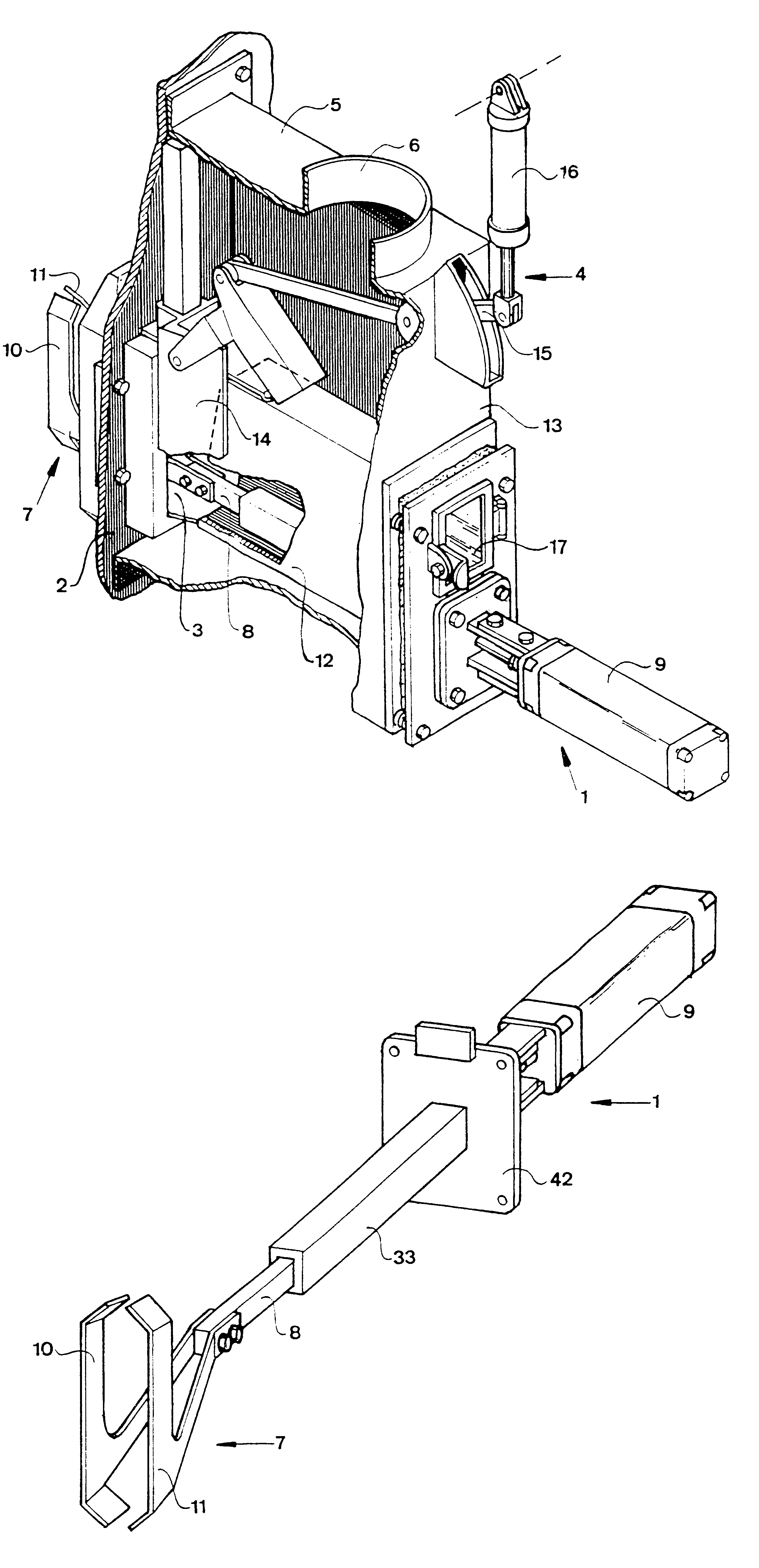
A partially sectioned perspective view of the device according to the invention according to a first preferred embodiment is illustrated in FIG. 1. The device comprises on one hand an arrangement 1 for cleaning an air port 3 arranged in a wall 2 of a furnace from dust particles and flowing cinder products from the interior of the furnace, and on the other an arrangement 4 for regulating the flow of air through the air port 3.

The furnace is especially a soda house furnace, and the device is especially suited for regulating and cleaning air ports of such a soda house furnace, but also other applications are conceivable for the device according to the invention. Such a soda house furnace or recovery boiler comprises a number of such air ports distributed around the furnace wall above the level of the spent liquor located in the furnace. A first series of air ports are called primary air ports, and a second and a third series of air ports on levels in a vertical direction above the firs...


PUM


Abstract

A device for regulating and cleaning an air port (3) arranged in the wall (2) of a furnace, especially a soda house furnace, comprises a cleaning arrangement (1) and an arrangement (4) for regulating the air flow through the air port, in which an air casing (5) is arranged around the air port on the outer side of the furnace wall, in which a drum (12) is arranged inside the air casing and air-tightly connected to the wall of the air casing located opposite to the furnace wall. An opening defined by at least a cover member (14) of the regulating arrangement and at least one lateral wall of the drum is arranged with a restricted extension in the circumferential direction of the drum so as to achieve an air jet in towards and through the air port (3).

Description

FIELD OF THE INVENTION AND PRIOR ARTThe present invention relates to a device for regulating and cleaning an air port (3) arranged in a wall (2) of a furnace, especially a soda house furnace, comprising a cleaning arrangement (1), which in it turn comprises a cleaning member (7) movable with respect to the walls of the air port (3), and arrangement (4) for regulating the air flow through the air port (3), and air casing (5) being arranged around the air port (3) on the outer side of the furnace wall (2), a drum (12) being arranged inside the air casing (5) and connected to a wall (13) of the air casing (5) located opposite to the furnace wall (2), the cleaning arrangement (1) being also connected to the wall (13) of the air casing (5) and extending at least partially through the drum (12), the regulating arrangement having a cover member (14) movable with respect to the drum (12), the cleaning member (7) being movable between two end positions and independently of the position of th...

Claims


Application Information

Patent Timeline
Patent Type & Authority Patents(United States)
IPC IPC(8): F23L13/00F23L1/00F23L13/06F23L9/00
CPCF23L1/00F23L9/00F23L13/06
Inventor ERIKSSON, TORE
Owner LT PROD SKUTSKAR
Why Eureka
Try Eureka