
Ferrite magnet powder and magnet using said magnet powder, and method for preparing them

a technology of ferrite magnet powder and magnet powder, which is applied in the direction of ferroso-ferric oxide, magnets, iron compounds, etc., can solve the problems of reducing remanence, ferrite magnets cannot exhibit sufficient coercivity and saturation magnetization, and ferrite magnets cannot be developed sufficiently. , to achieve the effect of improving sinterability, reducing remanence, and reducing remanen

Inactive Publication Date: 2002-07-16
SUMITOMO SPECIAL METAL CO LTD
View PDF9 Cites 13 Cited by
  • Summary
  • Abstract
  • Description
  • Claims
  • Application Information

AI Technical Summary

Benefits of technology

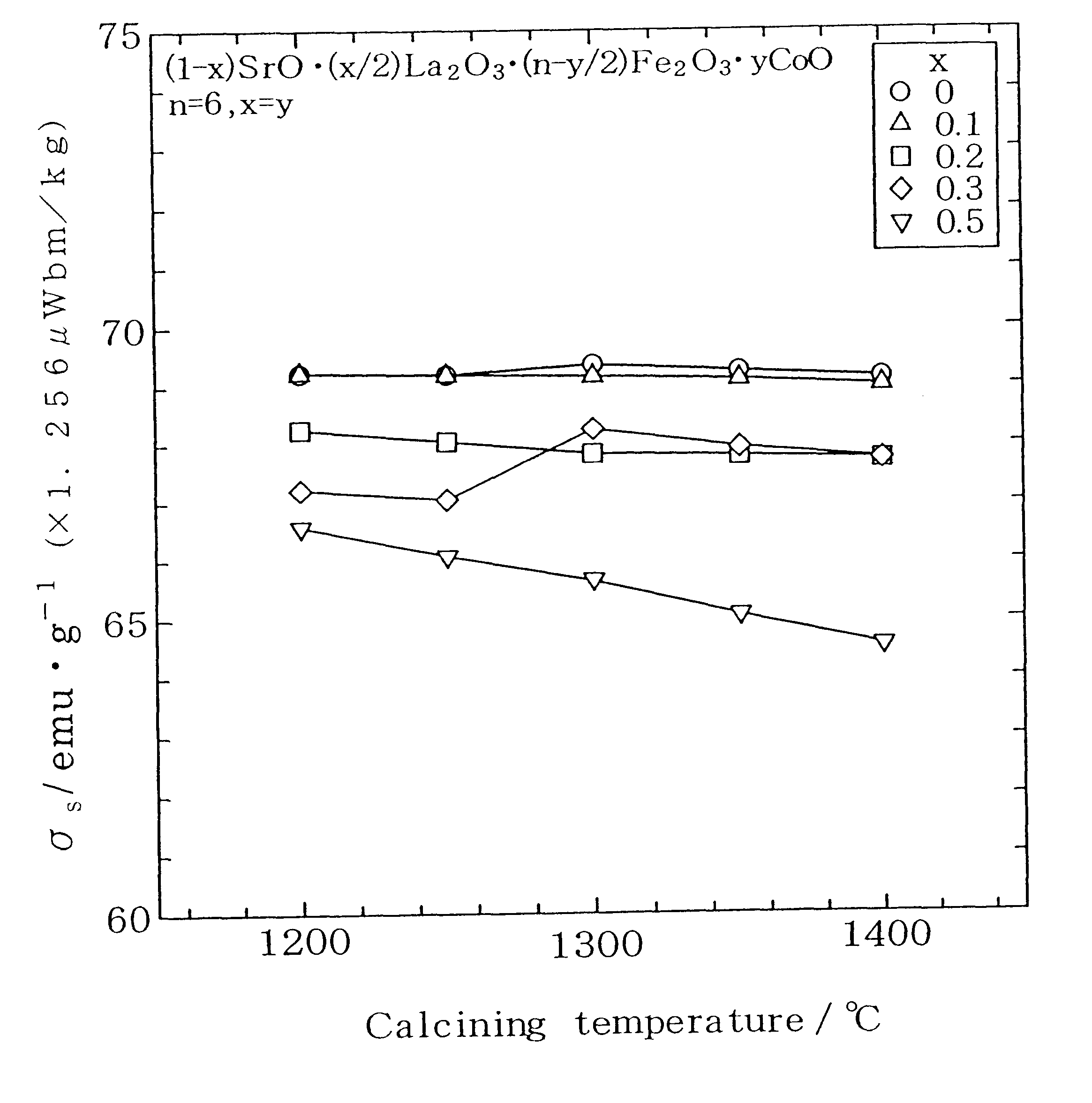
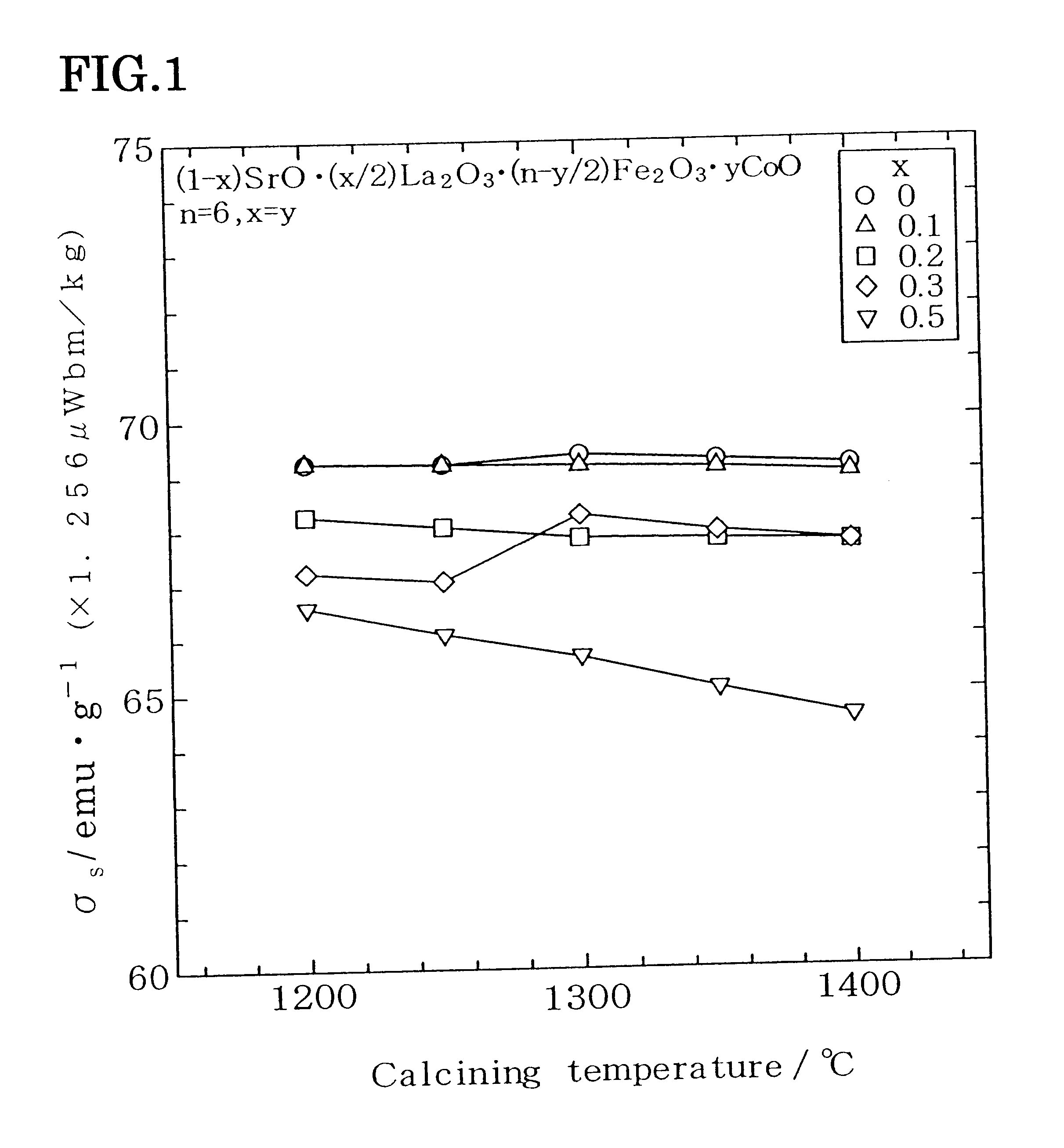
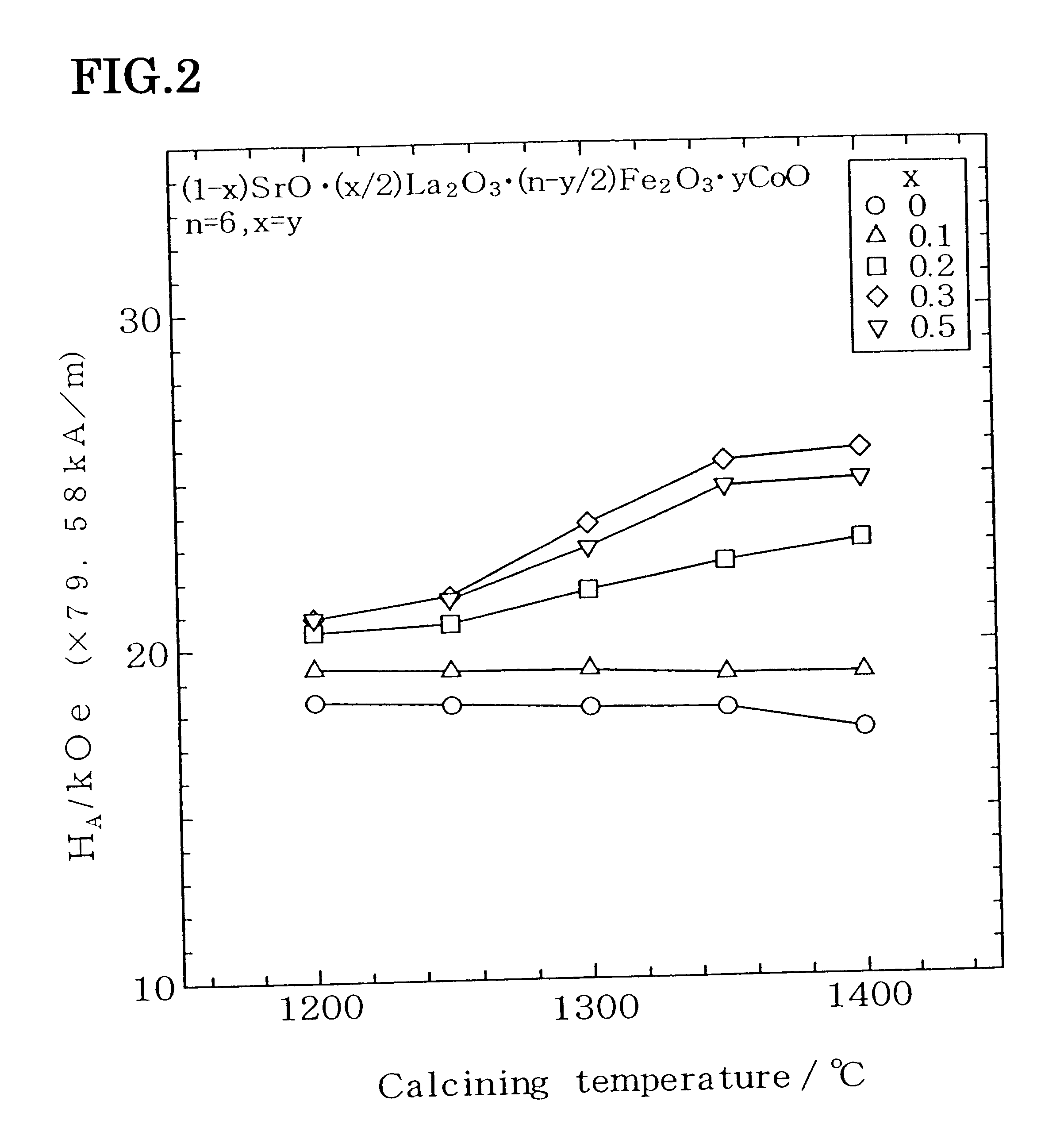
The present inventors found that if La and Co are added to a source material blended powder and if the mixture is calcined at a temperature higher than 1300.degree. C., then coercivity (i.e., magnetic anisotropy field) can be increased while suppressing the decrease in saturation magnetization. This is probably because the sites where Fe is replaced with Co change with the rise in calcining temperature, thus improving the magnetic properties. More specific reasons are as follows.

Problems solved by technology

Conversely, if the grain sizes are controlled with the addition of Al.sub.2 O.sub.3, for example, to increase the coercivity, then the density of the sintered compact decreases, resulting in decrease of the remanence.
However, it has been difficult to develop a ferrite magnet with its remanence and coercivity both improved.
However, even these ferrite magnets cannot exhibit sufficiently improved coercivity and saturation magnetization.
In addition, neither coercivity nor remanence seems to be sufficiently improvable.

Method used


Image

  • Ferrite magnet powder and magnet using said magnet powder, and method for preparing them
  • Ferrite magnet powder and magnet using said magnet powder, and method for preparing them
  • Ferrite magnet powder and magnet using said magnet powder, and method for preparing them

Examples


Embodiment Construction

First, a source material powder with a composition represented as (1-x)SrO.(x / 2)La.sub.2 O.sub.3.(n-y / 2)Fe.sub.2 O.sub.3.yCoO, which was compounded such that x=y=0.3, was calcined at 1350.degree. C., thereby preparing the inventive magnet powder.

Next, the magnet powder was finely pulverized to a size of 0.52 .mu.m. Then, CaCo.sub.3 =0.7 wt % and SiO.sub.2 =0.4 wt % were added to the resulting finely pulverized powder and blended together. The finely pulverized, blended powder was shaped in a magnetic field and then sintered at 1230.degree. C. for 30 minutes, thereby obtaining a sintered magnet.

The magnetic properties of the resultant sintered magnet were: remanence Br of 0.44T; coercivity H.sub.CJ of 4.6.times.79.58 kA / m; and (BH).sub.max of 4.7.times.7.958 kJ / m.sup.3.

Industrial Applicability

According to the present invention, calcine and magnet powder can have their saturation magnetization and coercivity both improved at the same time. Thus, a magnet with excellent magnetic proper...


PUM

PropertyMeasurementUnit
temperatureaaaaaaaaaa

Abstract

An La-Co ferrite magnet powder, in which Sr and Fe are replaced with La and Co, respectively, is made by carrying out a calcination process at a temperature higher than 1300° C. and equal to or lower than 1450° C. Fe has a magnetic moment oriented upwardly with respect to a crystal c-axis at a number of sites thereof, and also has an opposite magnetic moment oriented downwardly with respect to the crystal c-axis at another number of sites thereof. And Fe is replaced with Co at the greater number of sites thereof. As a result, high coercivity is attained. In this manner, coercivity can be increased while suppressing decrease in saturation magnetization sigmas.

Description

The present invention relates to ferrite magnet powder, magnet made from the magnet powder and methods for making the powder and the magnet.Ferrite is a generic term for various compounds containing an oxide of a divalent anionic metal and trivalent iron and has found a wide variety of applications in motors, electric generators, and so on. Typical materials for a ferrite magnet include Sr or Ba ferrites with a magnetoplumbite hexagonal structure (SrFe.sub.12 O.sub.19 or BaFe.sub.12 O.sub.19). Each of these ferrites can be made from iron oxide and a carbonate of strontium (Sr) or barium (Ba) at a relatively low cost by a powder metallurgical process.A basic composition of a magnetoplumbite ferrite is usually represented by a chemical formula of MO.nFe.sub.2 O.sub.3, where M is a metal element to be divalent anions and is selected from the group consisting of Sr, Ba, Pb and so on. In the ferrite, iron ions (Fe.sup.3+) located at respective sites have spin magnetic moments and are bon...

Claims


Application Information

Patent Timeline
Patent Type & Authority Patents(United States)
IPC IPC(8): C04B35/26H01F1/032H01F1/11C01G49/00C01G51/00
CPCC01G49/0018C01G49/009C01G51/006C04B35/2633C04B35/2641C04B35/62645C04B35/62675H01F1/113H01F41/0273C01P2002/52C01P2002/54C01P2002/72C01P2004/61C01P2004/62C01P2006/42C04B2235/3208C04B2235/3213C04B2235/3227C04B2235/3274C04B2235/3275C04B2235/3418C04B2235/5445C04B2235/76C04B2235/767C04B2235/786H01F1/11
Inventor TOYOTA, SACHIOHOSOKAWA, SEIICHIANAMOTO, SHUJIFURUCHI, ISAMU
Owner SUMITOMO SPECIAL METAL CO LTD
Learn More