
RFeB-BASED SINTERED MAGNET PRODUCTION METHOD AND RFeB-BASED SINTERED MAGNETS

a technology of rfeb and rfeb, which is applied in the direction of magnets, manufacturing tools, magnetic bodies, etc., can solve the problems of increasing the rfeb /sub>h /sub>content, reducing the maximum energy product (bh)/sub>max, and comparatively low coercivity h/sub>cj /sub> among various magnetic properties, etc., to achieve a large amount of thickness

Inactive Publication Date: 2016-10-13
INTER METALLICS KK +1
View PDF4 Cites 12 Cited by
  • Summary
  • Abstract
  • Description
  • Claims
  • Application Information

AI Technical Summary

Benefits of technology

The present invention provides a method for easily obtaining an RFeB system sintered magnet with improved coercivity that is bonded together with a boundary portion that has increased electric resistivity, suppressing the influence of eddy current during use. Additionally, the invention allows for the obtention of an RFeB system sintered magnet with a great thickness that cannot be easily treated by conventional grain boundary diffusion methods but still has RH diffused into regions near the center of the magnet.

Problems solved by technology

Earlier versions of the RFeB system sintered magnet had the defect that the coercivity HcJ was comparatively low among various magnetic properties.
On the other hand, increasing the RH content unfavorably reduces the residual magnetic flux density Br and consequently decreases the maximum energy product (BH)max.
Increasing the RH content is also undesirable in that RH are rare elements and their production sites are unevenly distributed globally.
If such an RFeB system sintered magnet is used in a motor or similar device, an eddy current induced by an externally applied changing magnetic field cannot easily flow beyond the boundary of the unit sintered magnets.

Method used


Image

  • RFeB-BASED SINTERED MAGNET PRODUCTION METHOD AND RFeB-BASED SINTERED MAGNETS
  • RFeB-BASED SINTERED MAGNET PRODUCTION METHOD AND RFeB-BASED SINTERED MAGNETS
  • RFeB-BASED SINTERED MAGNET PRODUCTION METHOD AND RFeB-BASED SINTERED MAGNETS

Examples


embodiments

(1) Production Method for RFeB System Sintered Magnet

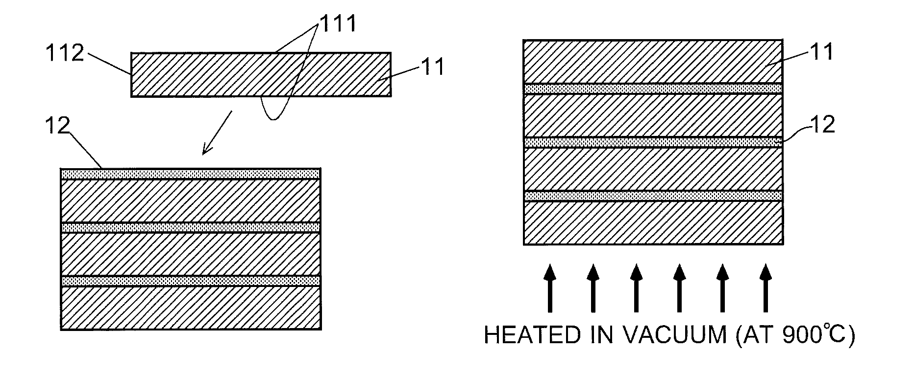
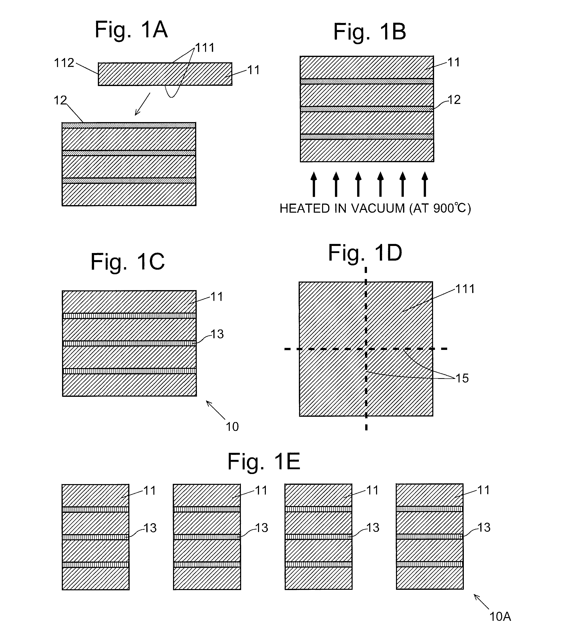
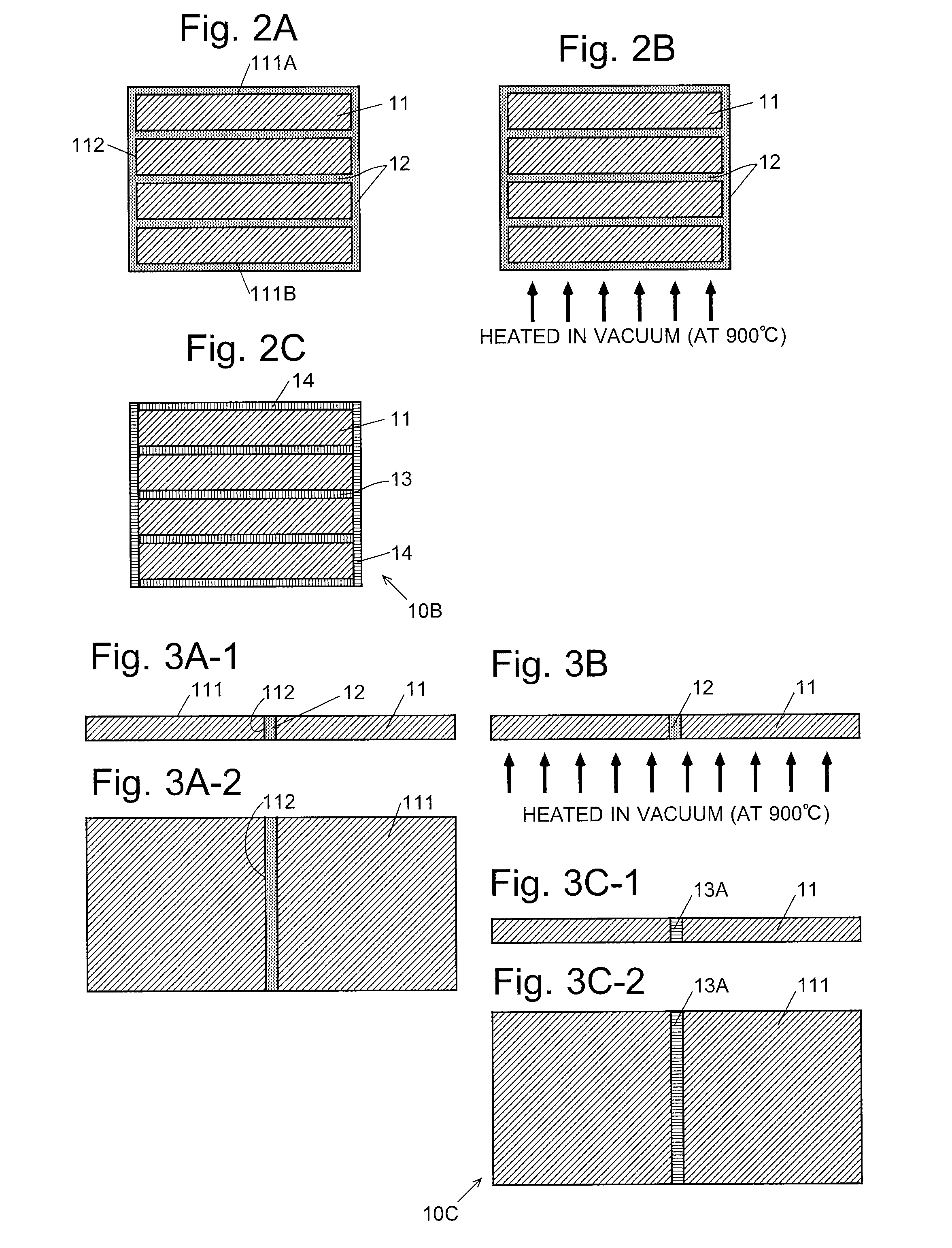
[0026]The production method for the RFeB system sintered magnet of the present embodiment includes the following processes: (1-1) creation of unit sintered magnets, (1-2) preparation of a paste made from a metallic powder containing a heavy rare-earth element RH (which is hereinafter called the “RH-containing metallic powder”) and an organic matter mixed together, and (1-3) creation of an RFeB system sintered magnet including two or more unit sintered magnets bonded together, using the unit sintered magnets and paste prepared in the previous processes. These processes are hereinafter sequentially described.[0027](1-1) Creation of Unit Sintered Magnets

[0028]Initially, a raw-material alloy containing 25-40% by weight of RL and 0.6-1.6% by weight of B, with the balance being Fe and unavoidable impurities is prepared. A portion of RL may be replaced by other rare-earth elements, such as RH. A portion of B may be replaced by C. A porti...


PUM

PropertyMeasurementUnit
sizeaaaaaaaaaa
particle sizeaaaaaaaaaa

Abstract

A method for producing RFeB system sintered magnet composed of at least two unit sintered magnets bonded to each other at flat bonding surfaces, each unit sintered magnet composed of crystal grains whose main phase is made of R2Fe14B containing, as a main rare-earth element R, light rare-earth element RL wherein at least one element selected from the group of Nd and Pr. Paste prepared by mixing organic matter and metallic powder containing at least one element selected from heavy rare-earth elements RH of Dy, Ho and Tb is sandwiched between neighboring unit sintered magnets, and a grain boundary diffusion treatment is performed. Coercivity is improved by this grain boundary diffusion treatment. Since an oxide or similar compound of RH and / or RL is formed at boundary of unit sintered magnets, the influence of eddy current during a period of use is suppressed, and unit sintered magnets are strongly bonded together.

Description

TECHNICAL FIELD[0001]The present invention relates to a method for producing an RFeB system sintered magnet whose main phase is made of R2Fe14B containing, as its main rare-earth element R, at least one element selected from the group of Nd and Pr, as well as an RFeB system sintered magnet produced by the same method. The “RFeB system sintered magnet” is not limited to a magnet which does not contain any other element than Nd and / or Pr, Fe and B; it may also contain a rare-earth element which is neither Nd nor Pr, or contain other elements such as Co, Ni, Cu or Al.BACKGROUND ART[0002]RFeB system sintered magnets were discovered in 1982 by Sagawa (one of the present inventors) and other researchers. The magnets have the characteristic that most of their magnetic characteristics (e.g. residual magnetic flux density) are far better than those of other conventional permanent magnets. Therefore, RFeB system sintered magnets are used in a variety of products, such as driving motors for hy...

Claims


Application Information

Patent Timeline
Patent Type & Authority Applications(United States)
IPC IPC(8): B23K20/02C22C38/10C22C38/06C22C38/00B22F9/04B22F9/08B22F1/00B22F3/00B22F3/10B22F5/00C22C28/00B23K20/00B23K20/14H01F1/053H01F7/02C22C38/16B22F1/05B22F1/10B22F1/102
CPCB23K20/02B22F2302/45C22C38/10C22C38/06C22C38/005C22C38/002B22F9/04B22F9/08B22F1/0011B22F1/0062B22F3/004B22F3/10B22F5/006C22C28/00B23K20/002B23K20/14H01F1/0536H01F7/021B22F2009/044B22F2998/10B22F2304/058B22F2304/10C22C38/16C22C38/00B22F7/064C22C2202/02H01F1/0577H01F41/0293C22C38/02B22F2999/00B22F1/05B22F1/102B22F1/10B22F2202/05
Inventor SAGAWA, MASATOTAKAGI, SHINOBU
Owner INTER METALLICS KK
Learn More