
Wall reinforcement apparatus and method using composite materials

a technology of wall reinforcement and composite materials, applied in the field of wall reinforcement, can solve the problems of a costly and time-consuming procedure, a structurally inadequate structure, and a high probability of serious damage or possibly catastrophic failure,

Inactive Publication Date: 2002-07-16
ENGINEERED COMPOST SYST +1
View PDF6 Cites 57 Cited by
  • Summary
  • Abstract
  • Description
  • Claims
  • Application Information

AI Technical Summary

Benefits of technology

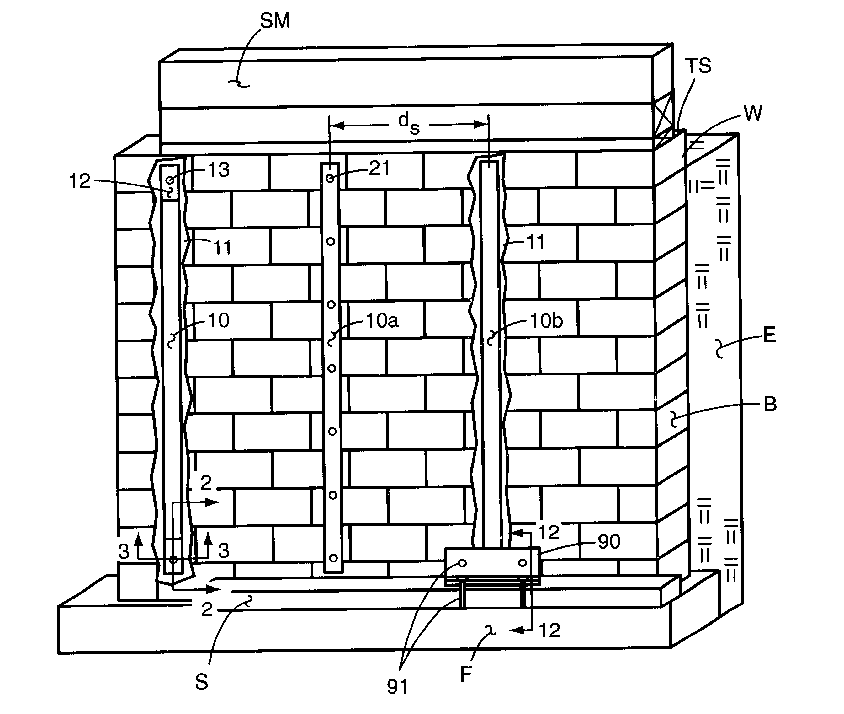
A major aspect of this invention is a method of strengthening vertically disposed masonry walls to increase their ability to resist laterally directed forces that may be applied to one surface of the wall. Once practiced, the method enhances the lateral strength of basement walls of residential homes and similar walls of commercial buildings. These walls are generally substantially subterranean with earth surrounding the building and disposed against the exterior surface of the wall.
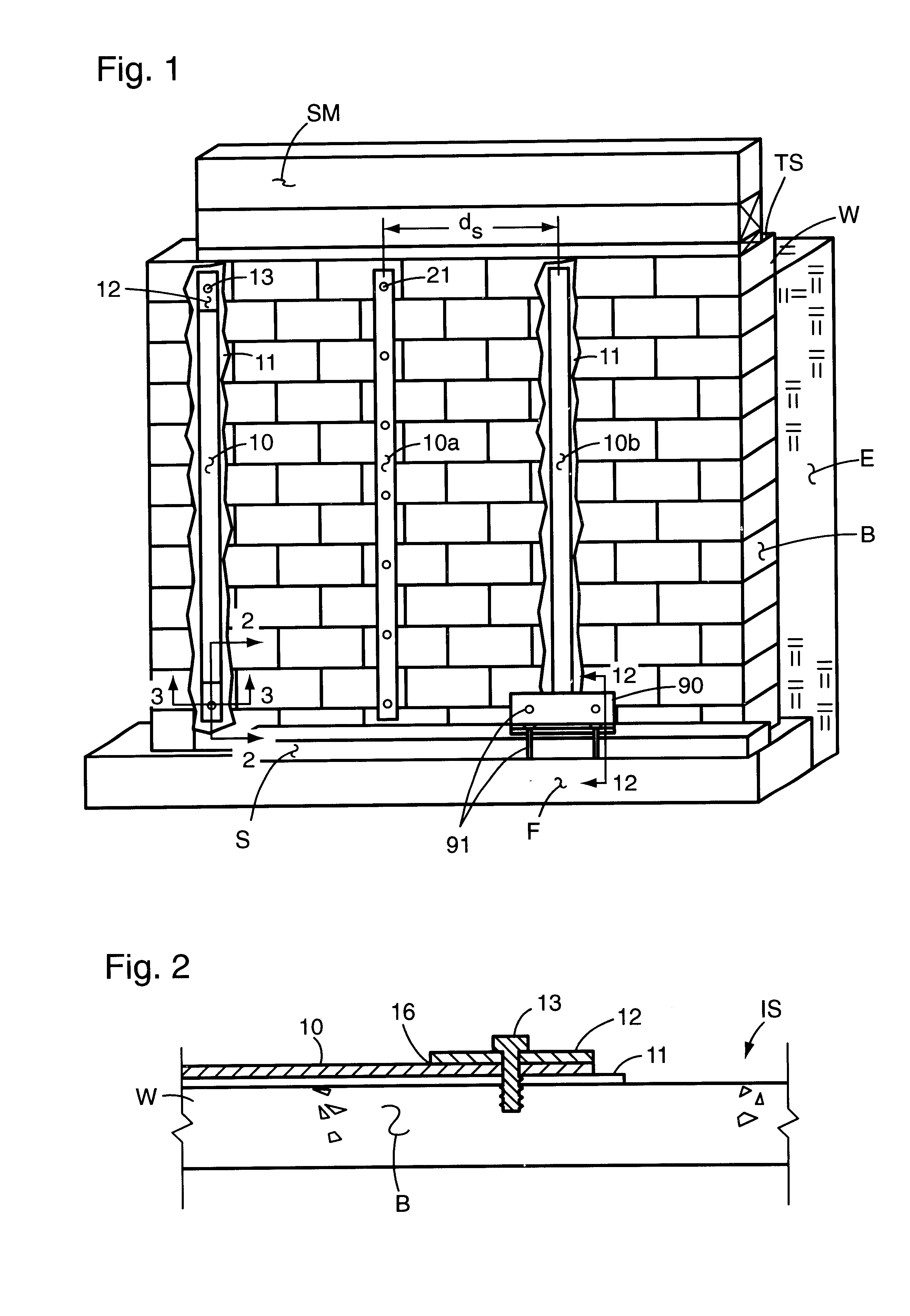
Mechanical anchoring of the plates to the wall at their top and bottom ends through use of fastening devices in combination with anchor plates is also contemplated to enhance the attachment strength of the plates to the wall. These anchor plates may be square sections of the reinforcing plate placed in overlying relationship to the outwardly facing surface of the plates and secured thereto by an adhesive bonding agent. Rectangular sections of the reinforcing plate may also be used, thereby distributing the anchoring force over an elongated length of a plate.
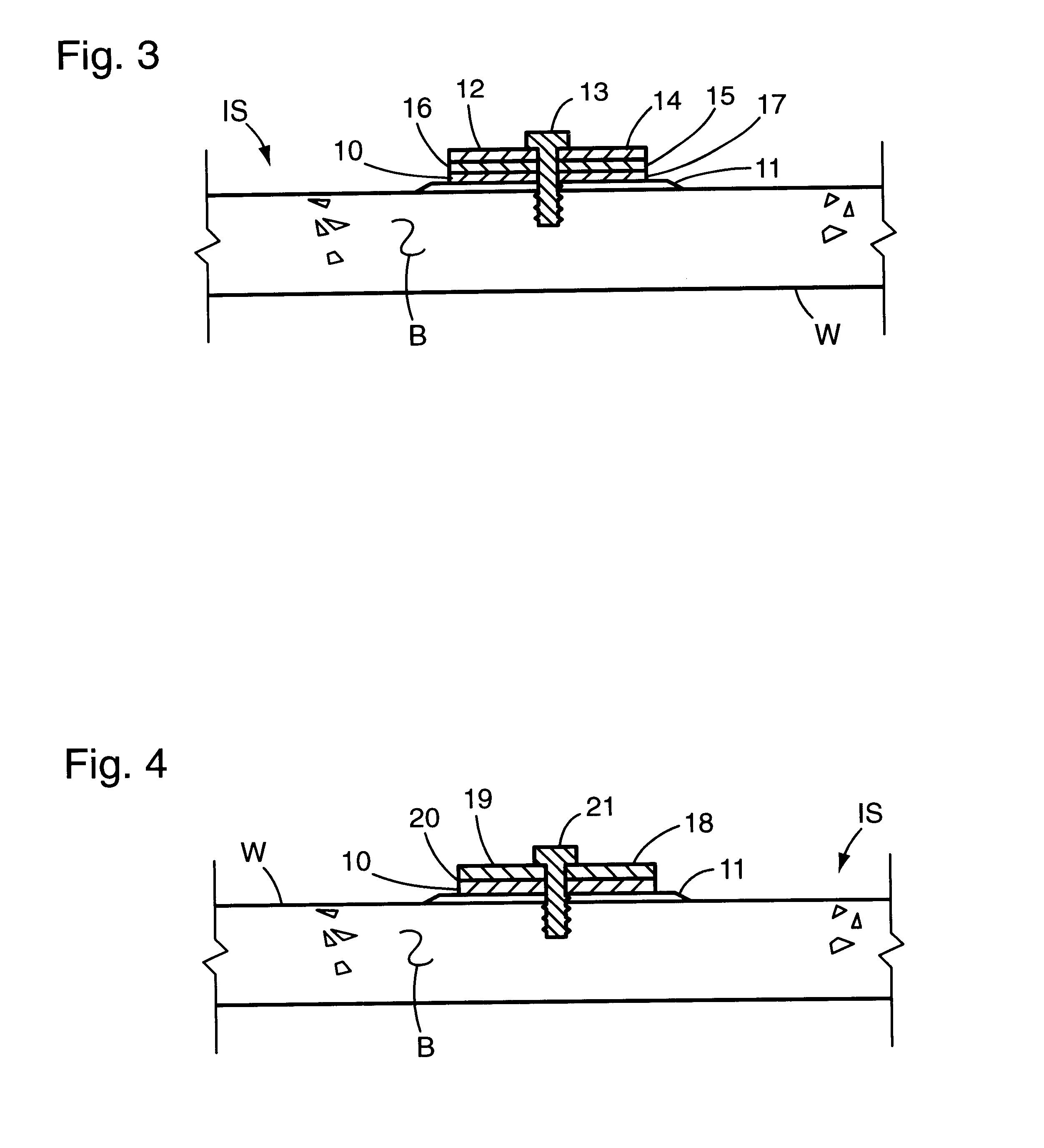
In a second embodiment of this invention the reinforced fibers are formed into a fabric-type sheet of material. The fibers are disposed in parallel, closely adjacent relationship forming a layer that is secured together by transversely extending high tensile strength fibers. This sheet is designed to be positioned in coplanar, overlying relationship to the interior surface of the masonry wall to which it is secured by a bonding resin, thereby providing waterproofing in addition to strengthening the wall.
Although the waterproofing sheet can be utilized by itself as described in the preceding paragraph it can also be used in combination with the rigid, fiber reinforced polymer plates. After application of the plates, the waterproofing sheet is applied. It may either be applied in a single, continuous sheet that overlies the vertically extending plates, or it may be applied in sections that fit between adjacently disposed pairs of the plates, and abut facing edges of each plate. The combination provides significant enhancement of the strengthening effect along with the added advantage of providing waterproofing.
Because a saturating adhesive can be absorbed too rapidly into the porous wall by capillary action, it is also an embodiment of the invention to apply a more highly viscous paste epoxy or other suitable filler to the wall prior to mounting the waterproofing sheet and the fabric strips to the wall. The paste adheres to the porous wall but prevents the lower viscosity saturating adhesive from being drawn from the fabric sheets or strips.
It is the primary objective of this invention, therefore, to provide an effective method of strengthening masonry or concrete walls of the type herein described after they have been constructed. This is accomplished by applying components at and near the interior surface of a wall thereby avoiding relatively costly work on the exterior of the wall.

Problems solved by technology

Any subterranean wall may at some subsequent time be found structurally inadequate to satisfactorily resist the horizontal force of the earth directed against the exterior surface of the wall W. There are many diverse factors that can cause a wall to become structurally inadequate to resist the forces exerted against its exterior surface, thus requiring some remedial action to prevent or lessen the likelihood of serious damage or possibly catastrophic failure.
This technique results in a structure that is not only objectionably intrusive into a basement's interior space but is a costly and time-consuming procedure.

Method used


Image

  • Wall reinforcement apparatus and method using composite materials
  • Wall reinforcement apparatus and method using composite materials
  • Wall reinforcement apparatus and method using composite materials

Examples


Embodiment Construction

Referring to the drawings, and in particular to FIG. 1 for this introductory description of an exemplary installation, a portion of a typical basement wall W of a residential building is shown as constructed in the known customary environment. That environment includes a footer F commonly fabricated from concrete and extending around the periphery of the building's excavation. It is normally rectangular in cross-section with an upper horizontal surface of greater width than the wall's thickness with the wall being built on that surface. The wall has a vertically extending interior surface IS and an outwardly facing exterior surface (not shown) which abuts the earth E that is filled in the excavated space after the wall is constructed. This earth illustrated in FIG. 1 is to be understood as being a continuation of a larger body of earth that surrounds the building, and provides the horizontal forces directed laterally against the wall's exterior surface. Recognition must also be give...


PUM

PropertyMeasurementUnit
Forceaaaaaaaaaa
Viscosityaaaaaaaaaa
Adhesion strengthaaaaaaaaaa

Abstract

A wall reinforcing method including reinforcing members adhered to the wall. The reinforcing members are either pre-cured composite plates or composite members formed in situ, that is, a fabric of reinforcing fibers that is saturated with an adhesive to form the matrix of the composite and to adhere the reinforcement to the wall. The in situ members are either strips of fabric or wide sheets that cover most of the wall. The spacing of the reinforcing members is determined, in one embodiment, by an array of spacing distances. The array, which is preferably in table form, is consulted by the installer who first measures some of the wall parameters and environmental characteristics.

Description

(C) STATEMENT REGARDING FEDERALLY-SPONSORED RESEARCH AND DEVELOPMENT(Not Applicable)(d) REFERENCE TO A "MICROFICHE APPENDIX"(Not Applicable)(e) BACKGROUND OF THE INVENTION1. Field of the InventionThis invention relates generally to reinforcement of walls, especially masonry walls of solid, unitary cast concrete construction or block walls. This invention also relates to reinforcement of walls constructed of wood, metal or other materials. More specifically, the invention relates to reinforcement of a wall by adhering fiber-reinforced polymer composite (FRPC) material to at least one surface of the wall.2. Description of the Related ArtThe earth adjacent a subterranean wall exerts a vertical force resulting from its weight, and it exerts a substantial horizontal force, due to its fluid properties, that increases in proportion to depth. Although this horizontal force is otherwise opposed and counteracted by the adjacent soil in other places within the earth, the wall, which is interpo...

Claims


Application Information

Patent Timeline
IPC IPC(8): E04G23/02
CPCE04G23/0218E04G2023/0251E04G2023/0262
Inventor MORTON, STEVEN E.
Owner ENGINEERED COMPOST SYST
Learn More