
Iron production method of operation in a rotary hearth furnace and improved furnace apparatus

a technology production method, which is applied in the direction of furnace types, blast furnace components, blast furnaces, etc., can solve the problems of difficult removal or discharge of purified solid iron and low carbon product from the furnace, and achieve the effect of improving the utilization of rotary hearth furnaces and high purity

Inactive Publication Date: 2002-07-02
MIDREX INT B V ROTTERDAM
View PDF25 Cites 73 Cited by
  • Summary
  • Abstract
  • Description
  • Claims
  • Application Information

AI Technical Summary

Benefits of technology

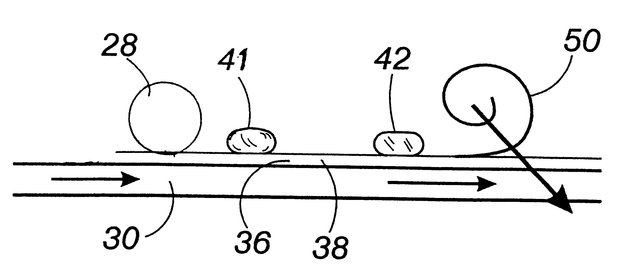
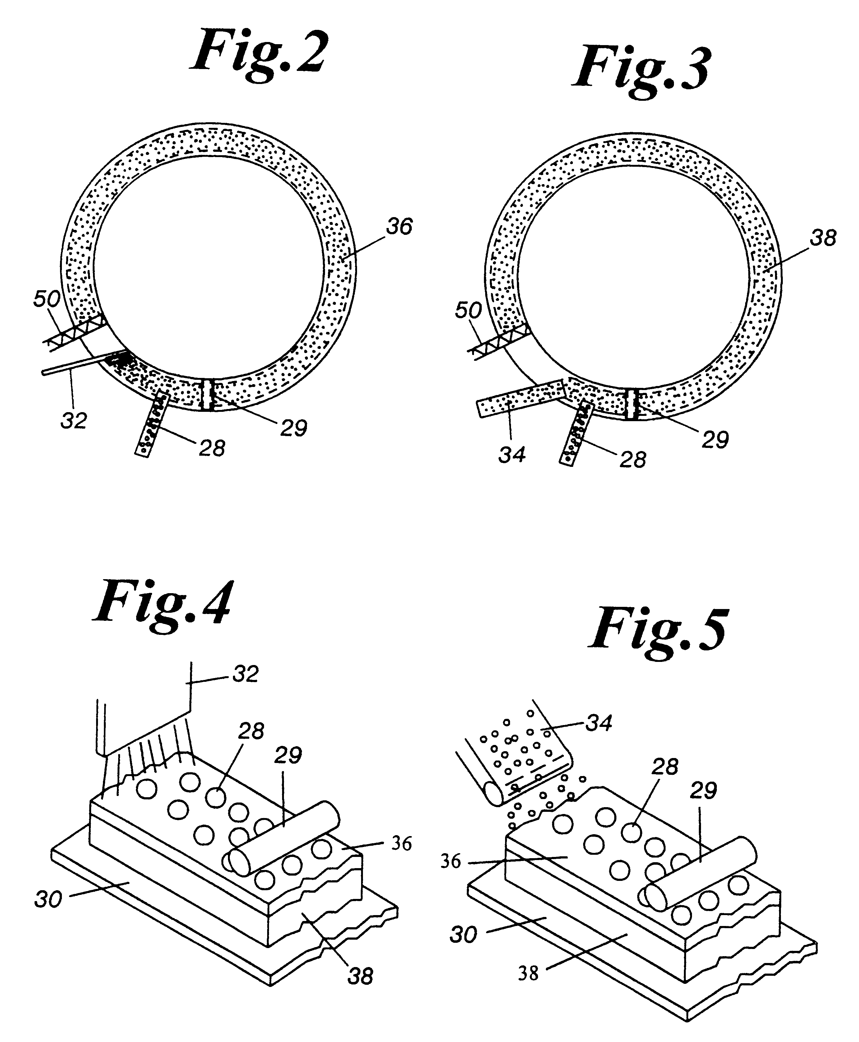
The solution effectively produces high purity iron with low carbon content by forming a protective coating on the hearth layer, preventing iron from adhering to the furnace and allowing for efficient discharge of solidified iron buttons separate from slag, thereby reducing losses and improving the quality of the iron product.

Problems solved by technology

Such a coating or bonding condition makes it difficult to remove or discharge the purified solid iron and low carbon product from the furnace.

Method used


Image

  • Iron production method of operation in a rotary hearth furnace and improved furnace apparatus
  • Iron production method of operation in a rotary hearth furnace and improved furnace apparatus
  • Iron production method of operation in a rotary hearth furnace and improved furnace apparatus

Examples


Embodiment Construction

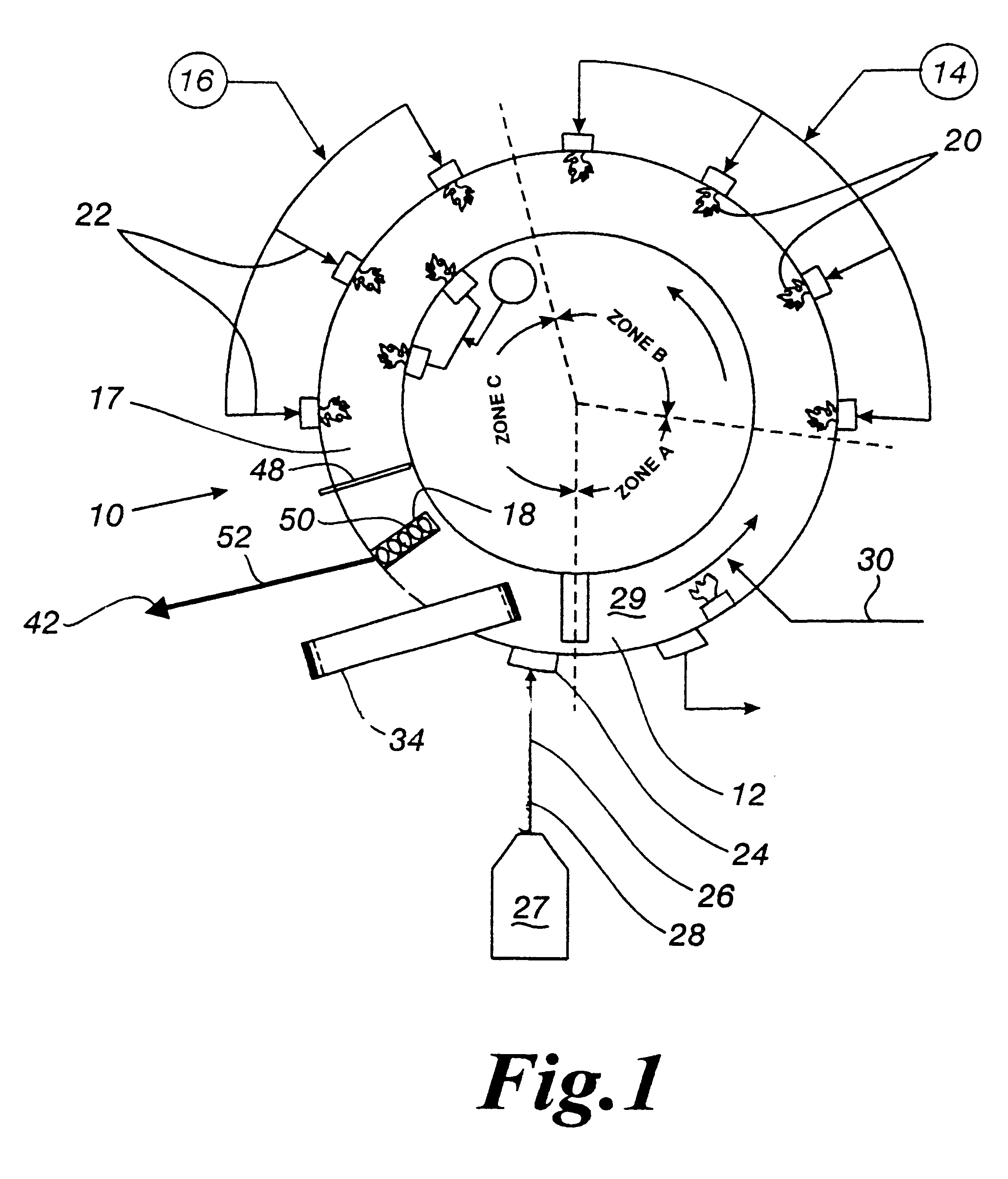
Referring now to the drawings, and more particularly to FIG. 1, a direct reduction furnace 10 is utilized for reducing iron oxide feed material. The furnace, such as a rotary hearth furnace (RHF) 10 has dimensions of a typical hearth furnace utilized in the iron production industry with an active hearth width of approximately 1 m to approximately 7 m width, or wider. The RHF 10 has a refractory layer surface or vitreous hearth layer surface 30 that is rotatable from a feed material zone 12, through approximately two or three burner zones 14, 16, 17, a reaction zone 17 and discharge zone 18 (see FIG. 1). The refractory layer surface or vitreous hearth layer surface 30 is rotatable in a repetitive manner from the discharge zone 18 to the feed material zone 12, and through the zones 12, 14, 16, 17, 18 for continuous operation. The burner zones 14, 1617 are each fired by a plurality of air / fuel, oil fired, coal fired, or oxygen enriched burners 20, 22.

The feed material zone 12 includes ...


PUM

PropertyMeasurementUnit
temperaturesaaaaaaaaaa

Abstract

The present invention is an apparatus and method for the direct reduction of iron oxide utilizing a rotary hearth furnace to form a high purity carbon-containing iron metal button. The hearth layer may be a refractory or a vitreous hearth layer of iron oxide, carbon, and silica compounds. Additionally, coating materials may be introduced onto the refractory or vitreous hearth layer before iron oxide ore and carbon materials are added, with the coating materials preventing attack of the molten iron on the hearth layer. The coating materials may include compounds of carbon, iron oxide, silicon oxide, magnesium oxide, and / or aluminum oxide. The coating materials may be placed as a solid or a slurry on the hearth layer and heated, which provides a protective layer onto which the iron oxide ores and carbon materials are placed. The iron oxide is reduced and forms molten globules of high purity iron and residual carbon, which remain separate from the hearth layer. An improved apparatus includes a cooling plate that is placed in close proximity with the refractory or vitreous hearth layer, cooling the molten globules to form iron metal buttons that are removed from the hearth layer. The improvements due to the present apparatus and method of operation provide high purity iron and carbon solid buttons, which are separate from slag particulates, and discharged without significant loss of iron product to the interior surfaces of the furnace.

Description

This invention relates to an apparatus and method for operation of an ore processing furnace for improved processing of iron oxide reduction. More particularly, this invention relates to the method of operation of a furnace for production of high purity iron and an improved furnace apparatus for iron reduction.In 1987, Midrex received U.S. Pat. No. 4,701,214, that taught reduction in a rotary hearth furnace and a method of operation which required less energy and a smaller smelting furnace by introducing reductant gases and fuel into the rotary hearth furnace.All major steelmaking processes require the input of iron bearing materials as process feedstocks. For a steelmaking method utilizing a basic oxygen furnace, the iron bearing materials are usually blast furnace hot metal and steel scrap. A broadly used iron source is a product known as Direct Reduced Iron ("DRI") which is produced by the solid state reduction of iron ore without the formation of liquid iron. DRI and / or steal sc...

Claims


Application Information

Patent Timeline
Patent Type & Authority Patents(United States)
IPC IPC(8): C21B13/00C21B13/10
CPCC21B13/10C21B13/105Y02P10/134
Inventor MEISSNER, DAVID C.HOFFMAN, GLENN E.SHOOP, KYLE J.NEGAMI, TAKUYAURAGAMI, AKIRATANIGAKI, YASUHIROITO, SHUZOKOBAYASHI, ISAOTSUGE, OSAMUTOKUDA, KOJIKIKUCHI, SHOICHI
Owner MIDREX INT B V ROTTERDAM
Learn More