
Low power SOI ESD buffer driver networks having dynamic threshold MOSFETS

a buffer driver and low-power soi technology, applied in pulse generators, instruments, pulse techniques, etc., can solve the problems of electrostatic discharge, and low current drivability of conventional diodes on soi

Inactive Publication Date: 2002-06-11
GLOBALFOUNDRIES INC
View PDF25 Cites 77 Cited by
  • Summary
  • Abstract
  • Description
  • Claims
  • Application Information

AI Technical Summary

Benefits of technology

In one aspect, the invention provides a structure, method and apparatus which uses a body-charging element in receiver and I / O driver circuits, peripheral circuits, and core circuitry in an SOI chip. The invention uses an SOI body-limiting element in receiver and I / O driver circuits, peripheral circuits, and core circuitry to provide a more robust network from overvoltage and electrical overstress in an SOI chip.
In addition, the invention provides a structure, method and apparatus which uses an SOI Lubistor elements for a body-reference network. The invention includes an SOI body- and gate-coupled MOSFET network for a body-modulation network and provides electrostatic discharge protection of SOI circuitry. The invention also provides a means for electrical overstress (EOS), electrostatic discharge (ESD), undershoot and overshoot protection to receiver, I / O driver and peripheral or core-circuitry for SOI circuitry. The invention uses a reference control network for SOI body potential modulation for receiver and I / O driver peripheral or core circuitry, for improved electrostatic discharge robustness of receiver and I / O drive peripheral circuitry and core circuitry.

Problems solved by technology

However, SOI circuits, like other electronic circuits, are: First, susceptible to electrostatic discharge (ESD), a surge in voltage (negative or positive) that occurs when a large amount of current is applied to the circuit; and second, in need of providing an ideality (a constant voltage swing of 60 mV / decade over several decades of current) for analog applications, such as in phase-locked-loop circuits, voltage regulators, and band gap reference circuits.
Traditional bulk overvoltage protection schemes, such as diode circuits, do not work well on SOI because of the presence of the SOI buried oxide.
That is, conventional diodes on SOI have small current drivability because the current is carried laterally and is limited by the thickness of the semiconductor material.

Method used


Image

  • Low power SOI ESD buffer driver networks having dynamic threshold MOSFETS
  • Low power SOI ESD buffer driver networks having dynamic threshold MOSFETS
  • Low power SOI ESD buffer driver networks having dynamic threshold MOSFETS

Examples


Embodiment Construction

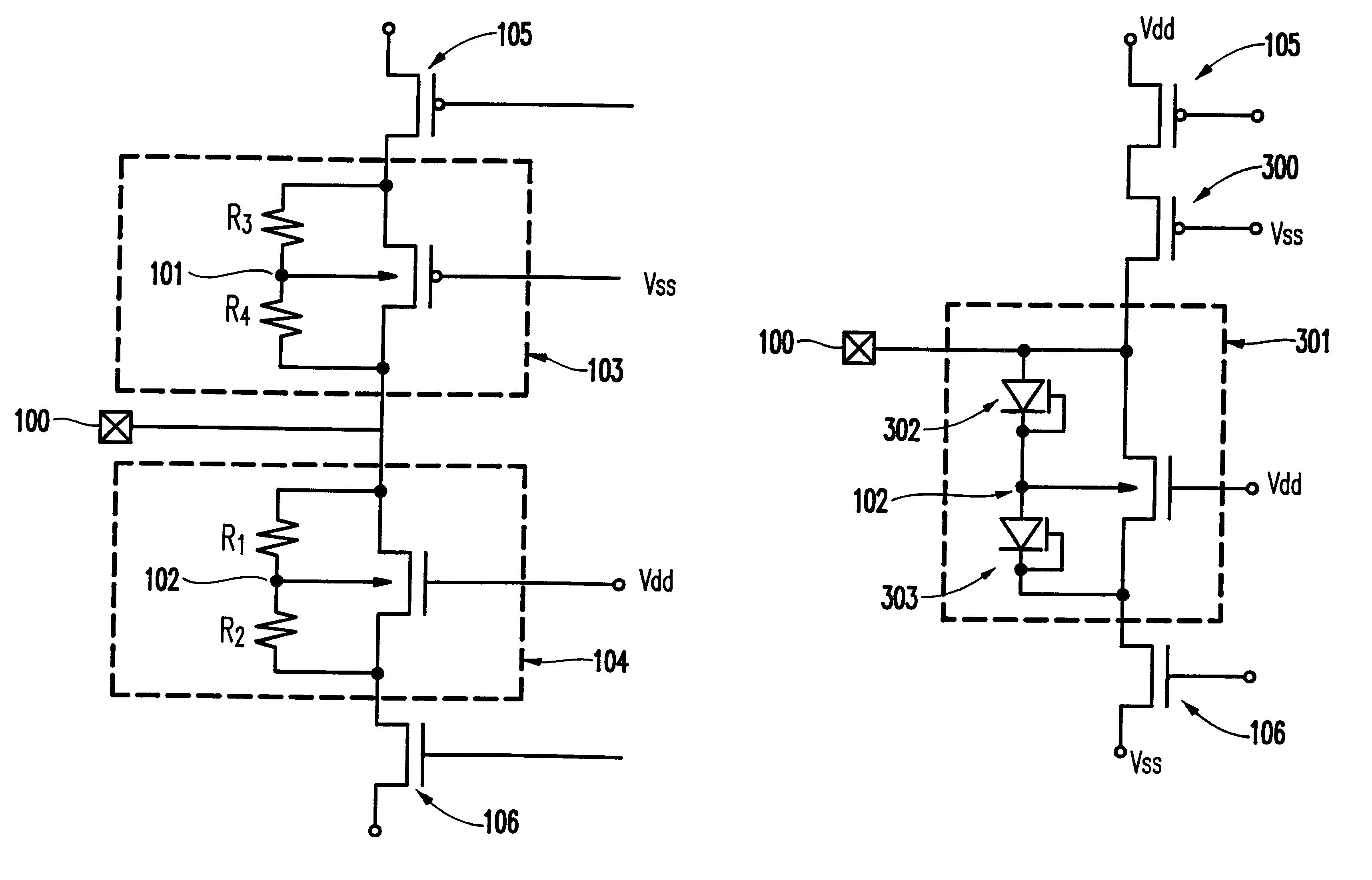
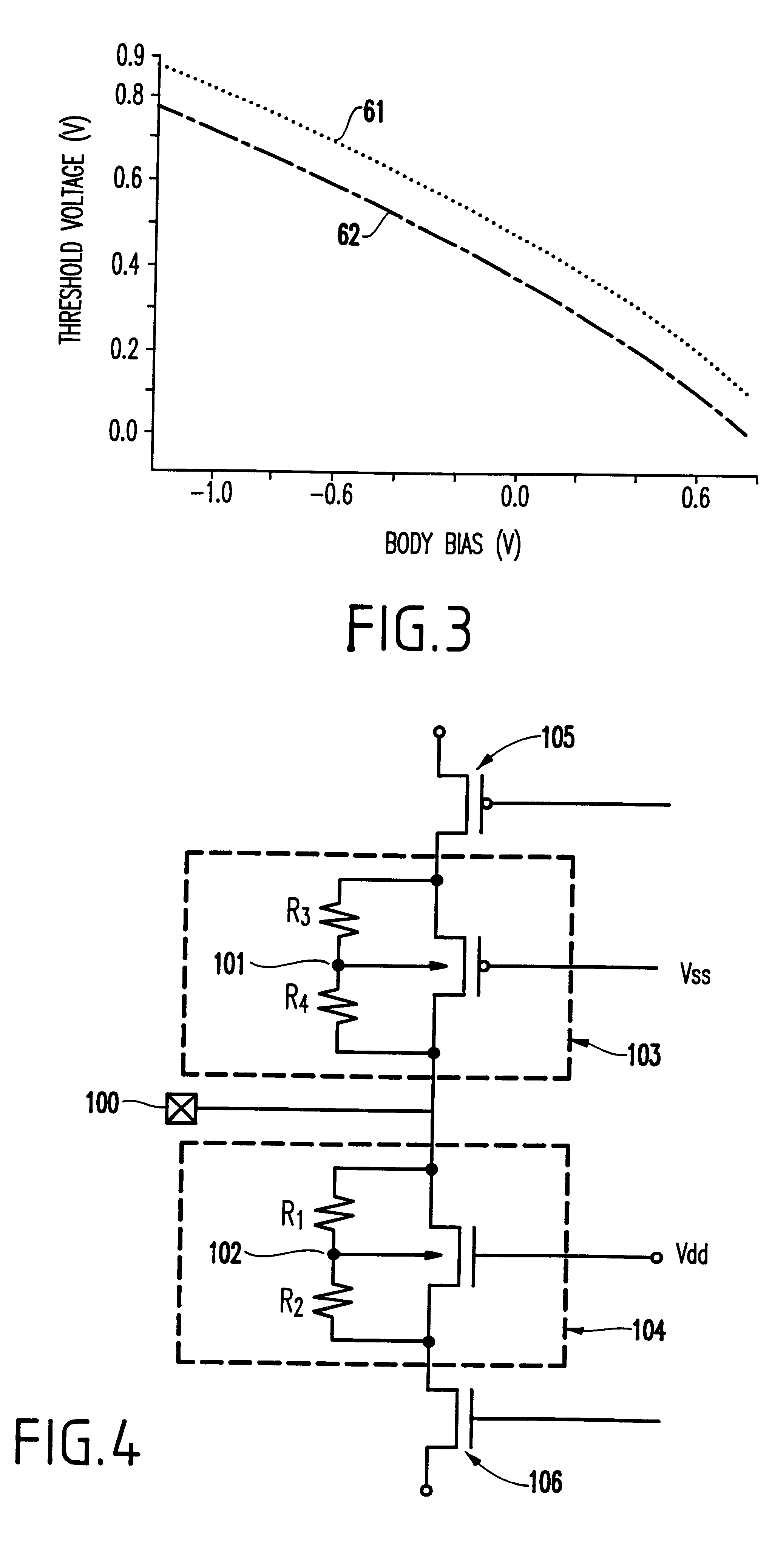
As mentioned above, ESD protection is becoming increasingly important in current technologies. Convention ESD protection devices can be destroyed if there are forced to accept excessive current. The invention described below allows the body to be tied to ground through the use of a network placed between the body and the ground. Therefore, the invention provides an ESD device which sinks substantially more current than the conventional devices.

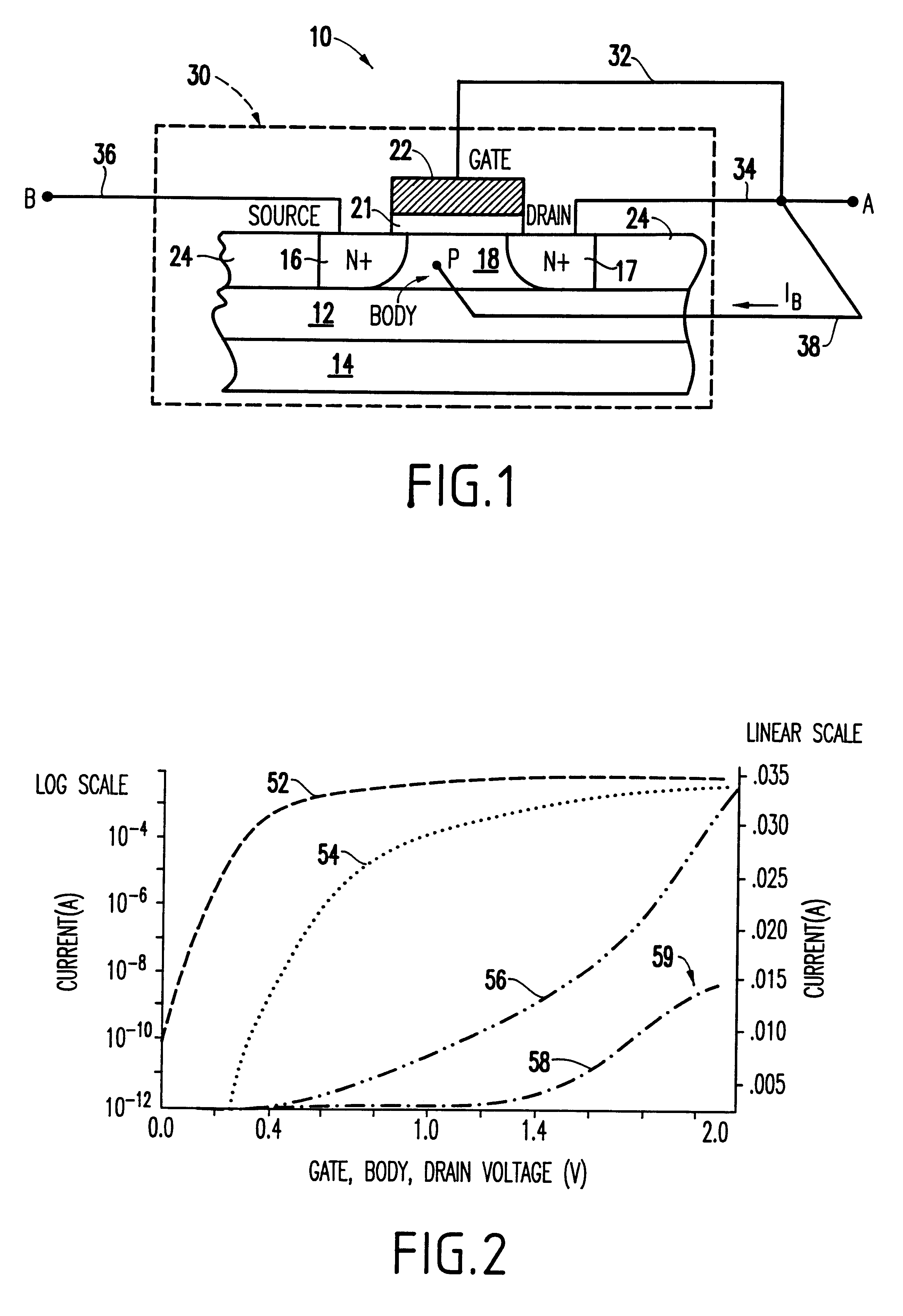
Using the dynamic threshold concepts explained above, the threshold voltage of a transistor can be reduced by letting the body of the transistor rise. The invention uses the drop of the threshold voltage to provide a higher current drive and greater ESD robustness or ESD current drive.

One approach to solving the aforementioned problems, mentioned in U.S. Pat. No. 5,811,857 to Assaderaghi et al. (hereinafter Assaderaghi) which is incorporated herein by reference, discloses a body-coupled gated (B / G-C) diode formed from an (SOI) field-effect tra...


PUM


Abstract

A method and structure for a body coupled driver circuit includes a pull-up stage having a first transistor and a pull-down stage having a second transistor. The first transistor and the second transistor have bodies coupled to either a reference voltage or a pad node.

Description

1. Field of the InventionThe invention generally relates to transistor devices which have a dynamic threshold and more particularly to a dynamic threshold device which has increased current capabilities.2. Description of the Related ArtSilicon-On-Insulator (SOI) technology, which is becoming of increasing importance in the field of integrated circuits, deals with the formation of transistors in a relatively thin layer of semiconductor material overlying a layer of insulating material. Devices formed on SOI offer many advantages over their bulk counterparts, including: higher performance, absence of latch-up, higher packing density, low voltage applications, etc. However, SOI circuits, like other electronic circuits, are: First, susceptible to electrostatic discharge (ESD), a surge in voltage (negative or positive) that occurs when a large amount of current is applied to the circuit; and second, in need of providing an ideality (a constant voltage swing of 60 mV / decade over several d...

Claims


Application Information

Patent Timeline
Patent Type & Authority Patents(United States)
IPC IPC(8): H01L27/02
CPCH01L27/0266H01L27/0255
Inventor VOLDMAN, STEVEN H.
Owner GLOBALFOUNDRIES INC
Learn More