
Communication system with an extended coverage area

Inactive Publication Date: 2005-09-22
KONINKLIJKE PHILIPS ELECTRONICS NV
View PDF13 Cites 16 Cited by
  • Summary
  • Abstract
  • Description
  • Claims
  • Application Information

AI Technical Summary

Benefits of technology

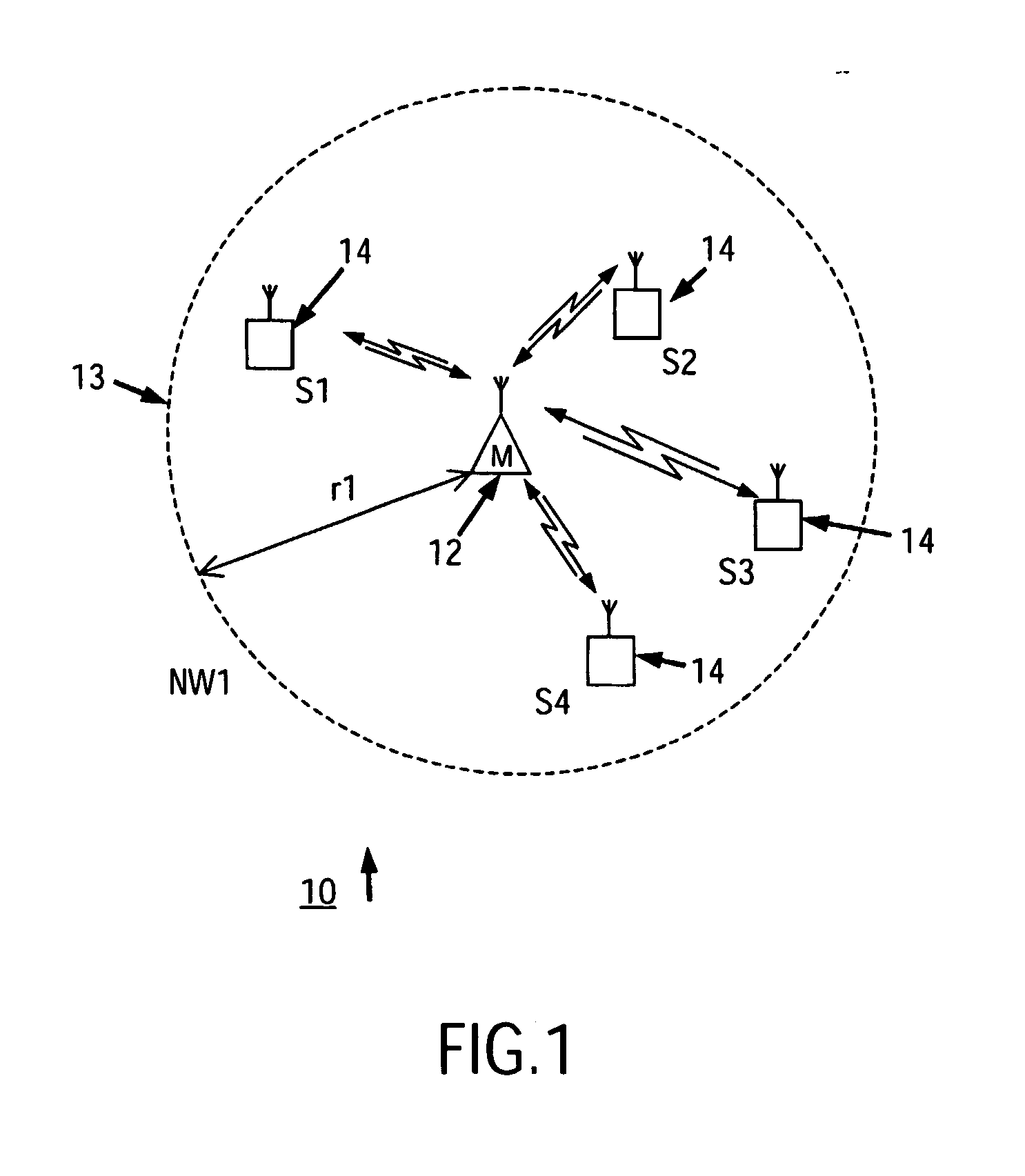
[0020] Thus a flexible infrastructure is provided enabling a greater coverage area and a more robust network to be obtained. Moreover the additional installation of secondary stations at a future date is eased with the chance of radio communication between the secondary stations and a primary station being increased without extensive radio coverage planning.

Problems solved by technology

However, a ZigBee radio communication system comprising a primary station and associated slave or secondary stations has, at the time of making this application, a limited radio coverage area related directly to the conventional radio broadcast range of the primary station which is estimated to be in the region of a few tens of metres for a ZigBee system communicating in one of the 16 channels defined in the 2.4 GHz ISM band.
A problem exists if a secondary station is transported out of the radio coverage area of its primary station, or is located in a poor radio reception area and therefore cannot receive or transmit messages to and from its primary station.

Method used


Image

  • Communication system with an extended coverage area
  • Communication system with an extended coverage area
  • Communication system with an extended coverage area

Examples


example message

[0041] Example Message Exchange process

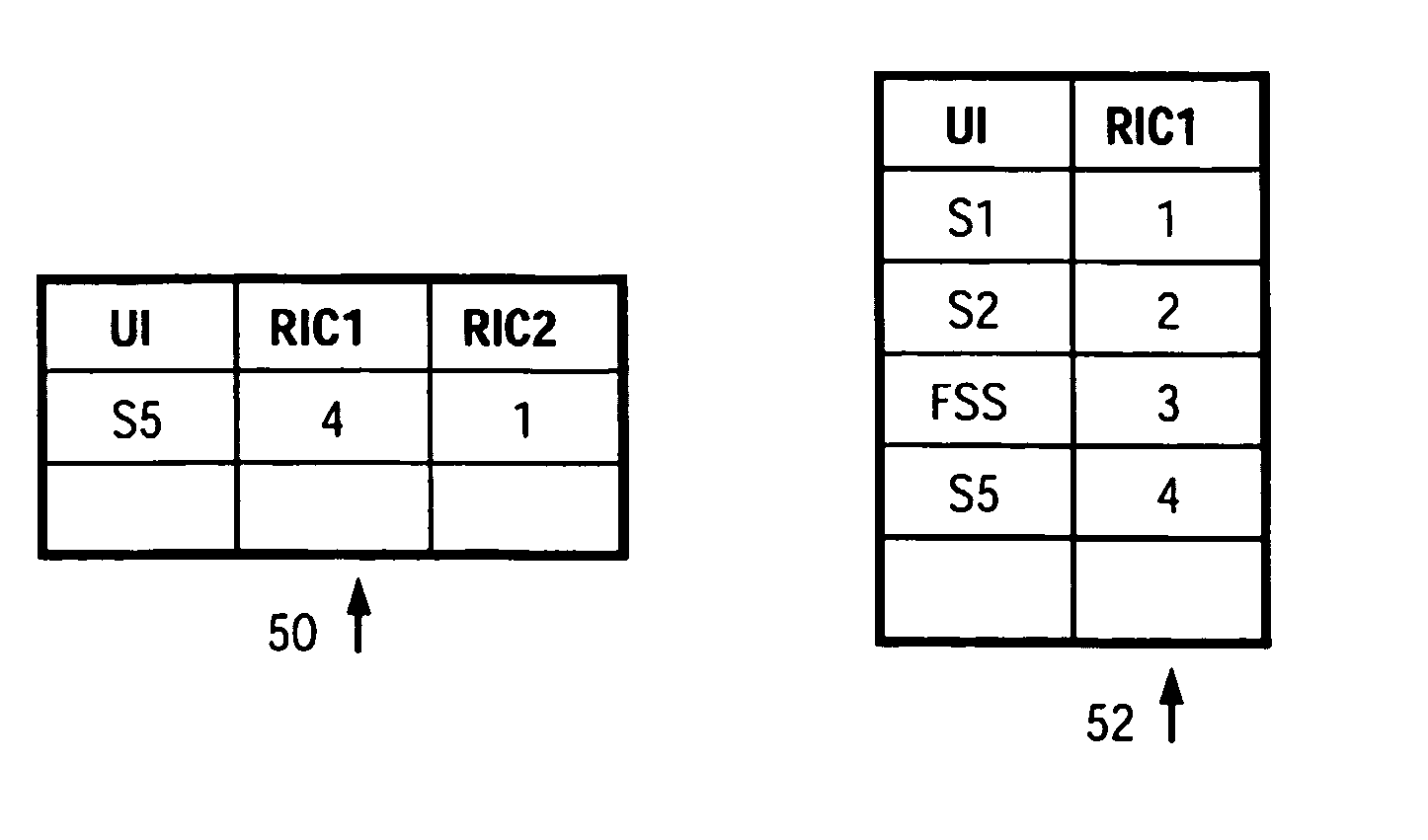
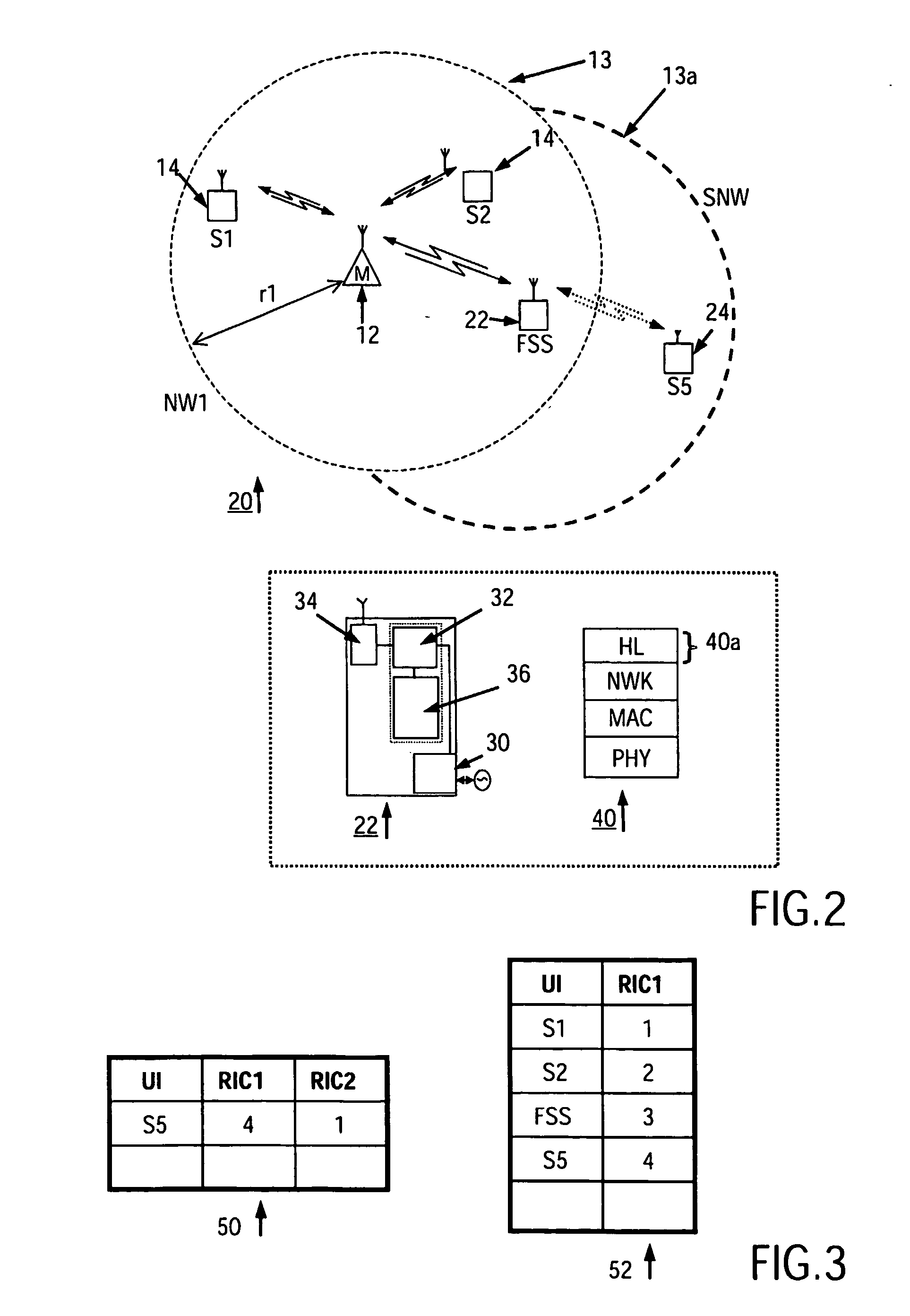
[0042] By following the process 58 of FIG. 4 the first secondary station 22 has stored in table 50 in memory 36 the radio code (RIC1) which the primary station has allocated to the further secondary station and also the radio code (RIC2) which it has allocated to the further secondary station 24. The further secondary station subsequently indicates a message as originating from itself by sending with the message its allocated RIC2. The further secondary station, on receiving such a message, looks up the associated RIC1 and transmits the message with the associated RIC1 value over the air to the primary station 12. This uplink portion of a message exchange process is illustrated by way of example in the flowchart 80 of FIG. 5.

[0043] Similarly, a message generated by the primary station 12 which is intended for the further secondary station 24 is transmitted with identity code RIC1 by the primary station. This is received by the first secondary ...


PUM


Abstract

A radio communication system (20) is described having a primary-secondary star-like topology, and wherein further secondary stations / devices (24) located outside of the radio coverage area (13) of the primary station are enabled to communicate with the primary station (12) via a first secondary station (22) located within the coverage area of the primary station (12). This is achieved by the first secondary station (22) registering the further secondary station(s) with both itself and the primary station (12), following which messages are exchanged between the primary station and the further secondary station(s) via the first secondary station according to translation of identity codes allocated at the time of registration.

Description

TECHNICAL FIELD [0001] The present invention relates to a method of extending the radio coverage area of a radio communication system, and further relates to radio devices / stations suitable for practising said methods. The present invention has particular, but not exclusive, application to low cost and low data rate master / slave radio communication systems. BACKGROUND ART [0002] Short range radio networks having a primary (or master) station which subsequently registers or associates secondary (or slave) stations with itself to form a master / slave radio communication system and network in which radio messages comprising data packets are exchanged between stations under the control of the primary station are generating much interest. The interoperability of such primary / secondary stations depends on each device having a predetermined and standardised radio protocol, such as those defined in the 802 family of radio standards adopted by the IEEE™. A well-known example of such a protoco...

Claims


Application Information

Patent Timeline
IPC IPC(8): H04B7/15H04B7/26H04L12/56
CPCH04L29/12254H04L61/2038H04W4/18H04L67/1002H04W88/04H04L69/04H04W8/26H04L61/5038H04L67/1001
Inventor AVERY, DAVID MMARSDEN, IAN A
Owner KONINKLIJKE PHILIPS ELECTRONICS NV
Learn More