
Apparatus for pumping out transfer chambers for transferring semiconductor equipment

a technology for semiconductor equipment and apparatus, which is applied in lighting and heating apparatus, charge manipulation, furnaces, etc., can solve problems such as effective substrate treatment, and achieve the effects of reducing the risk of polluting the atmosphere in the transfer chamber and therefore in the process chamber

Inactive Publication Date: 2002-06-11
ALCATEL LUCENT SAS
View PDF7 Cites 11 Cited by
  • Summary
  • Abstract
  • Description
  • Claims
  • Application Information

AI Technical Summary

Benefits of technology

Also, during the lowering of the pressure of the atmosphere in the airlock or in the transfer chamber, the substrate necessarily undergoes degassing, and it is important for the degassing to be sufficient before the substrate is inserted into the process chamber. Otherwise, the degassing continues in the process chamber, and the gases from that subsequent degassing constitute an additional pollution source during the treatment. Thus, another object of the invention is to improve the degassing of the substrates during their conditioning in the airlock or the transfer chamber, without delaying the transfer of the substrate to the process chamber.
To achieve these objects and others, the invention makes provision to control the lowering of the pressure of the atmosphere in the airlock or the transfer chamber during the conditioning, so as to avoid the appearance of any humidity or of any solidification of the gases.
By continuously monitoring the pumped gases, it is possible to prevent any condensation or solidification of the gases from occurring, and therefore to prevent any pollution from being brought into the process chamber. This monitoring also makes it possible to optimize the speed at which the pressure is lowered, to reach the mean speed as quickly as possible, so that the conditioning time is not increased, and so that it even becomes possible, within the conditioning time, to reduce the pressure to a lower value that facilitates degassing of the substrate.
In an advantageous embodiment, the system may further comprise pressure measurement means for measuring the pressure in a process chamber to which the transfer chamber is connected. It is thus possible to servo-control the pressure in the transfer chamber so as to avoid or to limit the transfer of pollutant matter from the process chamber to the transfer chamber. It is thus possible to increase the speed at which the following substrate is conditioned in the same transfer chamber, since this conditioning is not disturbed by pollution from the process chamber.
Preferably, the turbomolecular secondary pump may be of a robust type capable of operating as of the beginning of the pumping step by delivering the gases at atmospheric pressure. Thus, the turbomolecular pump is not associated with any branch pipe for starting pumping, and it constitutes the only pumping element connected to the transfer chamber. The risks of polluting the atmosphere in the transfer chamber and therefore in the process chamber are thus reduced.
Advantageously, it is possible to optimize the pumping speed to reach the appropriate pressure in a shorter time, and to continue the pumping until a minimum residual pressure is reached, and to maintain the residual pressure momentarily, e.g. until the end of conditioning, at a value lower than the appropriate operating pressure of the transfer chamber, thereby facilitating degassing of the substrate.

Problems solved by technology

The resulting solid or liquid elements then constitute pollution sources that work against effective treatment of the substrate in the process chamber.

Method used


Image

  • Apparatus for pumping out transfer chambers for transferring semiconductor equipment
  • Apparatus for pumping out transfer chambers for transferring semiconductor equipment

Examples


Embodiment Construction

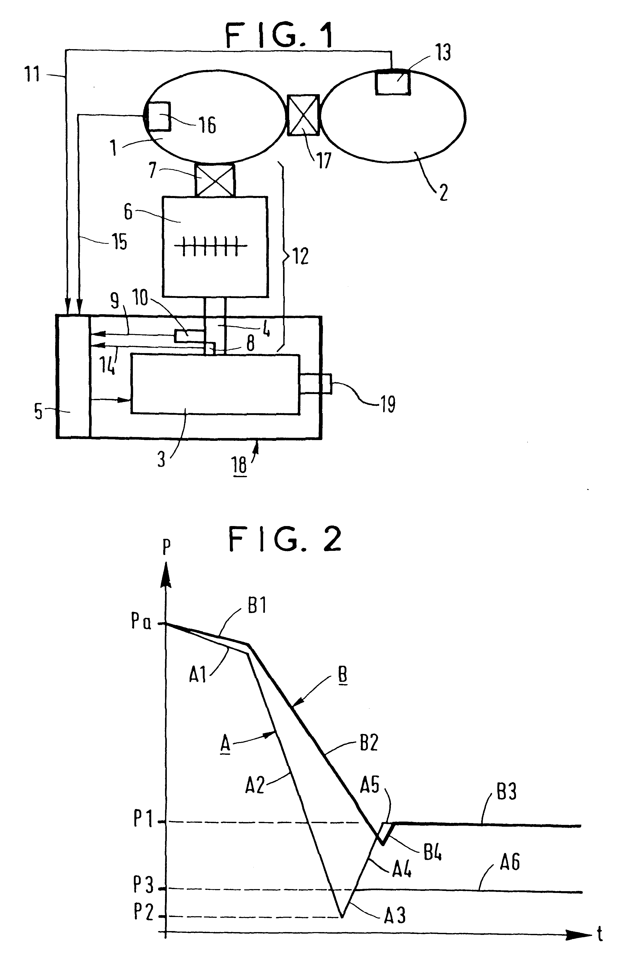
In the embodiment shown in FIG. 1, the pumping system of the invention makes it possible to pump gases out from an airlock or a transfer chamber 1 which is connected to a process chamber 2 via means enabling a semiconductor substrate to pass through.

The gas pumping system comprises a primary pump 3 driven by integrated drive means and connected to the airlock or the transfer chamber 1 via a pumping circuit 12 including a pipe 4 so as to pump the gases until an appropriate pressure is reached that is in the vicinity of the pressure in the process chamber 2. The drive means integrated in the primary pump 3 are suitable for pumping at a variable speed which is controlled by control apparatus 5 which may be of a type known per se.

A turbomolecular secondary pump 6 is interposed in the pumping circuit 12 between the pipe 4 connected to the primary pump 3 and the airlock or transfer chamber 1. An isolation valve 7 is interposed between the turbomolecular secondary pump 6 and the airlock or...


PUM

PropertyMeasurementUnit
pressuresaaaaaaaaaa
pressureaaaaaaaaaa
temperatureaaaaaaaaaa

Abstract

In the invention, the gases present in a transfer chamber are pumped out by means of a primary pump that is driven by variable-speed drive means, that is connected in series with a turbomolecular secondary pump, and that is associated with gas monitoring means for monitoring one or more appropriate characteristic parameters of the pumped gases and for producing control signals acting on the drive means of the primary pump so as to adapt its pumping speed in order to avoid any condensation or solidification of the gases in the airlock or transfer chamber. It is thus possible to optimize the speed at which the pressure is lowered, and to reduce the pollution brought into the process chamber.

Description

The present invention relates to methods and apparatus for pumping gases out from an airlock or transfer chamber for transferring semiconductors to a process chamber.In manufacturing semiconductor electronic components, an important step consists in treating a semiconductor substrate in a controlled atmosphere at very low pressure, e.g. for depositing layers of various materials by plasma deposition.In industrial production, substrates in the form of wafers are conditioned and brought successively into a process chamber through an airlock or through a transfer chamber inside which the atmosphere is brought progressively to an appropriate pressure similar to the pressure inside the process chamber. For that purpose, use is made of a gas pumping system comprising a primary pump driven by drive means and connected via a pumping circuit to the airlock or to the transfer chamber for pumping out the gases until the appropriate pressure is reached.In the process chamber, the atmosphere mus...

Claims


Application Information

Patent Timeline
Patent Type & Authority Patents(United States)
IPC IPC(8): C23C14/56C23C16/44H01L21/00B65G49/00H01L21/205H01L21/677
CPCC23C14/564H01L21/67017C23C16/4412C23C14/566
Inventor LAGEDAMONT, MARCBERNARD, ROLANDCHEVALIER, ERIC
Owner ALCATEL LUCENT SAS
Learn More