
Spinning reel face gear manufacturing method

a manufacturing method and technology for spinning reels, applied in fishing, hoisting equipment, other domestic objects, etc., can solve the problems of poor corrosion resistance, high relative density of zinc alloys, and poor corrosion resistance of zinc alloys, so as to improve corrosion resistance and improve the strength and precision of face gears so manufactured.

Inactive Publication Date: 2002-02-05
SHIMANO INC
View PDF2 Cites 23 Cited by
  • Summary
  • Abstract
  • Description
  • Claims
  • Application Information

AI Technical Summary

Benefits of technology

is to provide for the manufacture of face gears of improved corrosion resistance that ensures that the strength and precision of the face gears thus manufactured is maintained.
With a spinning reel face gear in connection with the present invention, because the tooth ring that is to be the meshing portion is formed of a separate material from the disk, it is possible to design a lightened face gear of improved anti-corrosiveness, maintaining its strength and precision, by manufacturing the disk with lightweight materials and materials that are anti-corrosive, and by manufacturing the tooth ring with materials by which its strength and precision are maintainable.

Problems solved by technology

With the conventional face gears, however, zinc alloys, which are of high relative density and are inferior in corrosion resistance, are utilized.
Thus the conventional use of zinc alloys impairs lightweight design, and makes improving corrosion resistance problematic.
Due to the inferior strength of aluminum alloys compared to zinc alloys, along with inferior manufacturing precision wherein die-casting or the like is to be carried out, however, when utilizing aluminum alloys as a face gear material, the strength and precision of the teeth of the face gears deteriorates.
Furthermore, while stainless steel alloys are of better strength compared to zinc alloys, owing to poor workability along with problems generally in injection molding, it is difficult to improve precision; when employing stainless steel alloys the precision of the face gear teeth is liable to deteriorate.
Herein, the disk is specially manufactured; if the disk were otherwise formed as a single body with the tooth ring, bending and warping are liable to occur depending on the thickness and weight.

Method used


Image

  • Spinning reel face gear manufacturing method
  • Spinning reel face gear manufacturing method
  • Spinning reel face gear manufacturing method

Examples


Embodiment Construction

Overall Configuration

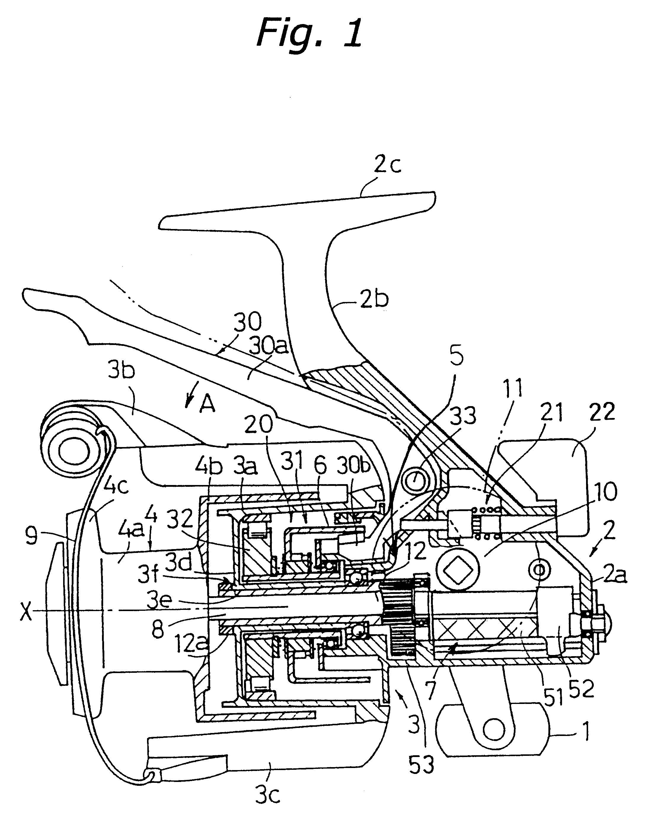
The spinning reel in which an embodiment of the present invention is adapted, shown in FIG. 1, is provided with: a reel main body 2 furnished with a handle 1; a rotor 3 supported for spinning on the front portion of the reel main body 2; and a spool 4 that winds on fish line and is disposed forward of the rotor 3.

The reel main body 2 has a body 2a, and a mount 2b is formed on its upper portion for mounting the spinning reel onto a fishing rod. The upper surface of the mount 2b forms a fitting portion 2c that attaches to a fishing rod. A rotor drive mechanism 5 for spinning the rotor 3; a rotor braking mechanism 6 for braking the rotor 3; and a level-wind mechanism 7 for uniformly winding fish line onto the spool 4 by shifting the spool 4 back and forth along rotational axis X; are provided in the interior of the body 2a.

The rotor 3 comprises a cylindrical member 3a and mutually opposing first and second arms 3b and 3c provided laterally of the cylindrical member...


PUM

PropertyMeasurementUnit
Strengthaaaaaaaaaa
Torqueaaaaaaaaaa

Abstract

A spinning reel face gear is manufactured by a method of molding tooth-ring bearing, obverse-facing gear teeth onto a separately formed gear disk after the gear disk is made. The gear disk is specially configured with circumferentially spaced peripheral indentations to retain the tooth ring strongly against torque when the face gear meshes with a pinion gear in operation in a spinning reel. Manufacturing the face gear in two separate stages adds a degree of freedom in material selection, allowing a lightweight material to be employed for the gear disk, and a high-strength material for forming precision gear teeth to be employed for the tooth ring. The two-stage manufacturing method also enables the tooth ring to be formed onto the gear disk in a mold that does not leave a parting line on the obverse, teeth-bearing face of the tooth-ring when the mold plates are parted.

Description

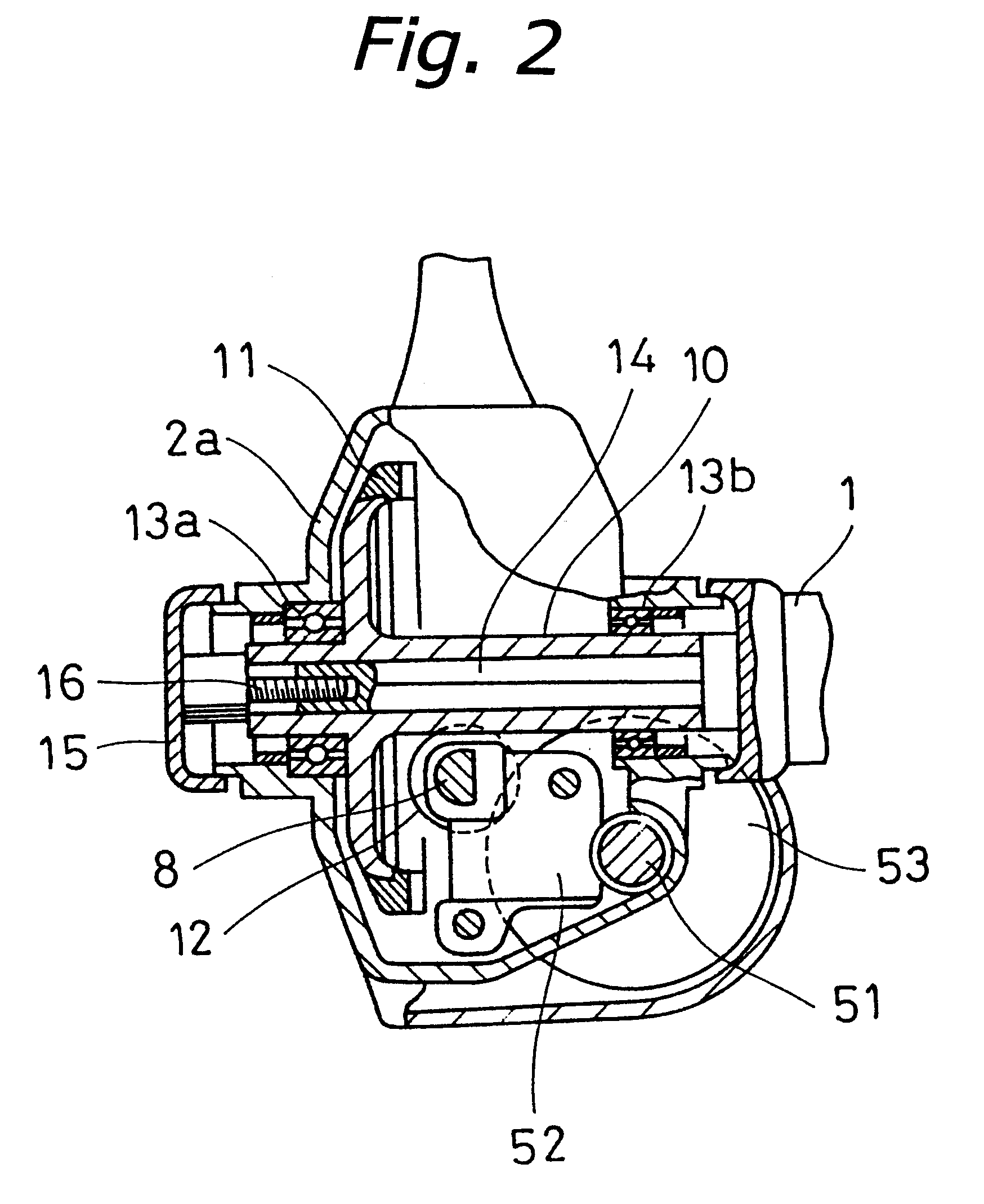
1. Technical FieldThe present invention relates to the manufacture of face gears provided on the handle shaft of spinning reels; in particular the invention relates to methods of diecasting such face gears.2. Description of Related ArtGenerally spinning reels have a reel main body, a rotor supported for free rotation on the main body, and a spool that peripherally winds on fish line, provided forward of the rotor. The rotor rotates unitarily with a pinion gear provided peripherally on the spool axle. The spool reciprocates back and forth by means of a level-wind mechanism that is driven by an intermediate gear that meshes with the pinion gear. The pinion gear meshes with a face gear (master gear) provided on a handle rotation axle (handle shaft) that is orthogonal to the pinion gear, and is rotated by rotation of the handle. The face gear is usually formed incorporated with the handle shaft. Conventionally zinc alloys have been comparatively widely used as a material for cheaply man...

Claims


Application Information

Patent Timeline
IPC IPC(8): A01K89/00A01K89/01F16H55/06
CPCA01K89/01F16H55/06Y10T29/49476Y10T29/4948
Inventor HITOMI, YASUHIRO
Owner SHIMANO INC
Learn More