
Desalination of seawater by evaporation in a multi-stack array of vertical tube bundles, with waste heat

Inactive Publication Date: 2001-10-30
SEPHTON HUGO H
View PDF7 Cites 39 Cited by
  • Summary
  • Abstract
  • Description
  • Claims
  • Application Information

AI Technical Summary

Benefits of technology

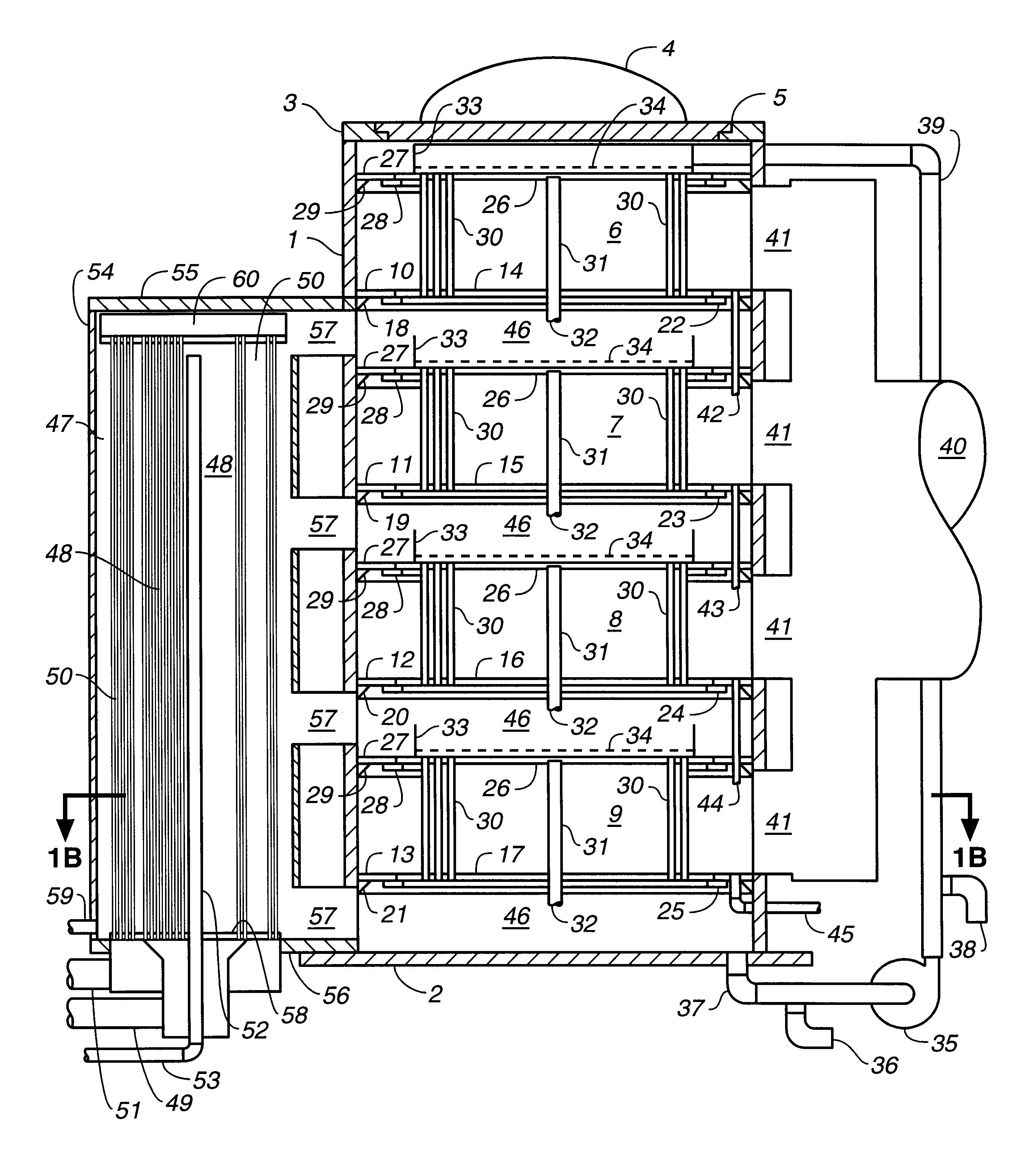
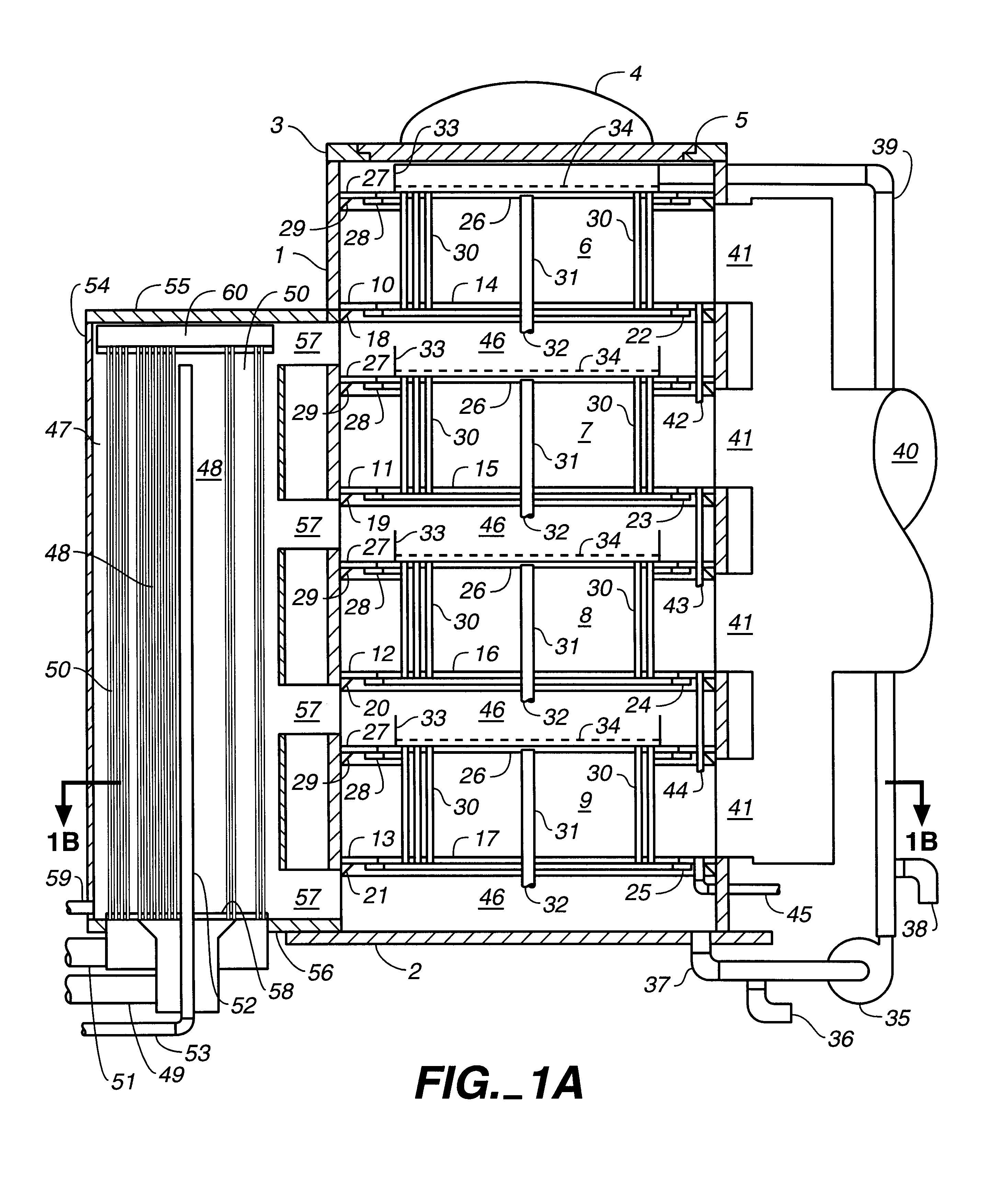
This invention is mainly about the design and operational or process aspects of a large seawater desalination system utilizing power plant turbine reject steam under vacuum which has no $-value or a very low value, or another source of waste heat to drive the distillation process. One examples of this invention uses a vertical tube bundles designed to have an acceptably low steam-side pressure drop and brine-side vapor pressure drop, which depends on the selection of the tube length and diameter when operated at a low temperature in the range of typically 100 to 130.degree. F. with a Delta-T in the range of typically 7 to 15.degree. F., and wherein several such tube bundles are assembled into a vertical stack unit sufficient to produce a targeted capacity of say a 1 million gallons per day (1 MGD) per unit, and wherein evaporation occurs in vertical stages wherein brine concentration increases or progresses stage to stage but the heating steam is of essentially a constant temperature and pressure for all evaporation or concentration stages; and which unit can be further sealed up by the addition more stacked bundles, or by using two or more such multi-stack units mounted side-by-side (or vertically) to provide a facility of 2, or 5, or 20 MGD capacity. For example, modules or units having more than 2 such stacked multiple bundles may be assembled, and may be mounted side-by-side within a common pressure vessel to provide larger evaporation capacities if sufficient waste heat is available. This multiple unit of stacks of vertically mounted multi-tube evaporator bundles or stages provides for a large evaporator facility having cascading flow or down-flow of feed liquid through the vertical stacks of tube bundles at essentially a constant steam temperature but at increasing concentration or salinity through the evaporator bundles or evaporation stages, and with parallel flow of the steam or heating fluid at essentially a constant or equal temperature or steam-side pressure to drive the evaporation process. The most significant advantages of this approach is that the cost of the pure water product can be lower than from any other present day desalination procedure, based mainly on the improvements of using waste steam to drive this evaporation system at no or low energy cost, and on this design for the assembly of large-capacity facilities based on a novel use of modular units of tube bundles stacked vertically for single-effect operation in a single pressure (or vacuum) vessel which provides improvements in the capital cost, in the feed pumping cost and in the energy cost needed. Tube bundles can be shop fabricated at low cost for field assembly of units.

Problems solved by technology

However, low Delta-T's impose high capital costs per effect as well as an increase in the product water cost.
The present target is what to do about waste heat, and the problem is that conventional evaporators have too small a capacity to handle it and cannot be scaled up by making their tube bundles taller or fatter, because both would reduce their efficiency unacceptably.
Also, the prior art multi-effect evaporators usually limit the Delta-T per effect to 3 to 5.degree. F. in order to justify or economize the high cost of steam under pressure, which in turn increases the capital cost as well as the product cost.

Method used


Image

  • Desalination of seawater by evaporation in a multi-stack array of vertical tube bundles, with waste heat
  • Desalination of seawater by evaporation in a multi-stack array of vertical tube bundles, with waste heat
  • Desalination of seawater by evaporation in a multi-stack array of vertical tube bundles, with waste heat

Examples


Embodiment Construction

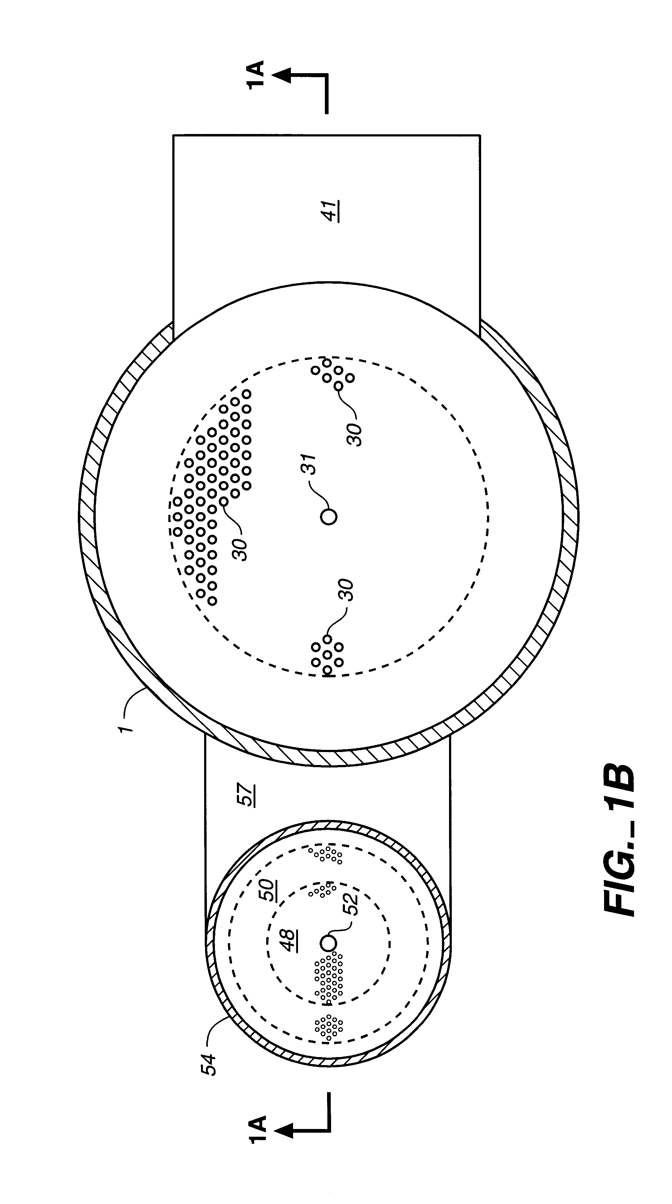
In the preferred and simples embodiment, a 4-stack vertical tube evaporator unit having a distillate capacity of about 1 MGD is represented by FIGS. 1A and 1B, with four stacked multi-tube bundles wherein the tube length and tube diameter as well as the number of tubes in the bundles and the number of tube bundles in the stack as well as the Delta-T applied are selected to cause liquid evaporation or distillation at a stated or desired capacity under certain or required conditions of steam temperature and coolant temperature, and wherein all the tubes in those bundles or stacks of bundles are operated under essentially the same or constant steam-side or shell-side temperatures or with steam from the same source, e.g. turbine reject steam, and wherein the liquid or brine to be evaporated or distilled passes sequentially through the tubes of the stacked tube bundles in downflow as the liquid is partially evaporated, or concentrated. Also, the liquid-side or tube-side is maintained at ...


PUM


Abstract

A large and economical type of multi-stack vertical tube evaporator (MS-VTE) is disclosed having units of multiple stacks of vertical tube bundles or stages mounted in a single vessel, and having its liquid feed pumped to the uppermost VTE bundle stack or stage and having the feed then cascading downward through the lower bundle stacks in series flow, and wherein all the tube bundles are heated with the same waste steam of no or low $-value, e.g. with turbine reject steam in parallel flow under vacuum into the steam-sides of all tube bundles in the unit through a common steam conduit; and wherein the feed liquid is progressively evaporated from stage to stage or stack to stack and the vapors produced in the tubes of each bundle during the partial evaporation of the feed are separated between the stacks and condensed by parallel flow into one or more condensers. Applied to seawater desalination in a co-generation procedure with a coastal power plant, this evaporator produces about one pound of distilled water per pound of turbine reject steam used under vacuum and applied to single-effect mode in one evaporator unit or several units mounted in a single vessel with a condenser, to substantially reduce the cost of such useful distilled water. When applied in a similar cogeneration procedure but in a multi-effect series mode of several such units, or multiple units, the rate of distilled water production can be increased several-fold based on the amount of turbine reject steam applied.

Description

(1) Field of the InventionThis invention relates to and is applicable to the desalination of seawater, brackish waters, industrial wastewater, municipal wastewater and, in general salty or saline water, or mining wastewater, by applying vertical tube evaporation or distillation.(2) Description of the Prior ArtKnown prior art related to this specification is described in the above U.S. Pat. No. 5,968,312 and in my U.S. Pat. No. 5,156,706 dated Oct. 20, 1992.The U.S. Pat. No. 5,968,312 is about feed flow control and its distribution into a multiplicity of parallel vertical flash-down channels and into the tubes of a multi-effect series of evaporators arranged in a vertical array of such effects for seawater desalination or liquid evaporation, and by utilizing steam under pressure at an elevated temperature. Feed flow control and its distribution are provided for with adjustable orifice plates mounted horizontally and spaced above the inlet ends of a multiplicity of tubes in each of th...

Claims


Application Information

Patent Timeline
IPC IPC(8): B01D1/06B01D1/00B01D1/26B01D3/00B01D3/06C02F1/04C02F1/16F28F27/00F28F27/02F28D7/16F28D7/00
CPCB01D1/065B01D1/26B01D3/065C02F1/04C02F1/16F28D7/1615F28D7/163F28F27/02Y10S203/18Y10S159/16Y10S203/21Y10S203/08Y10S159/08Y02A20/124
Inventor SEPHTON, HUGO H
Owner SEPHTON HUGO H
Learn More