
Curing system for photohardenable materials

a technology of photohardenable materials and cure systems, which is applied in the direction of process and machine control, optical radiation measurement, instruments, etc., can solve the problems of insufficient cure of photohardenable materials, light degradation over a period of time, and cos

Inactive Publication Date: 2001-10-30
AMERICAN DENTAL TECH
View PDF26 Cites 10 Cited by
  • Summary
  • Abstract
  • Description
  • Claims
  • Application Information

AI Technical Summary

Benefits of technology

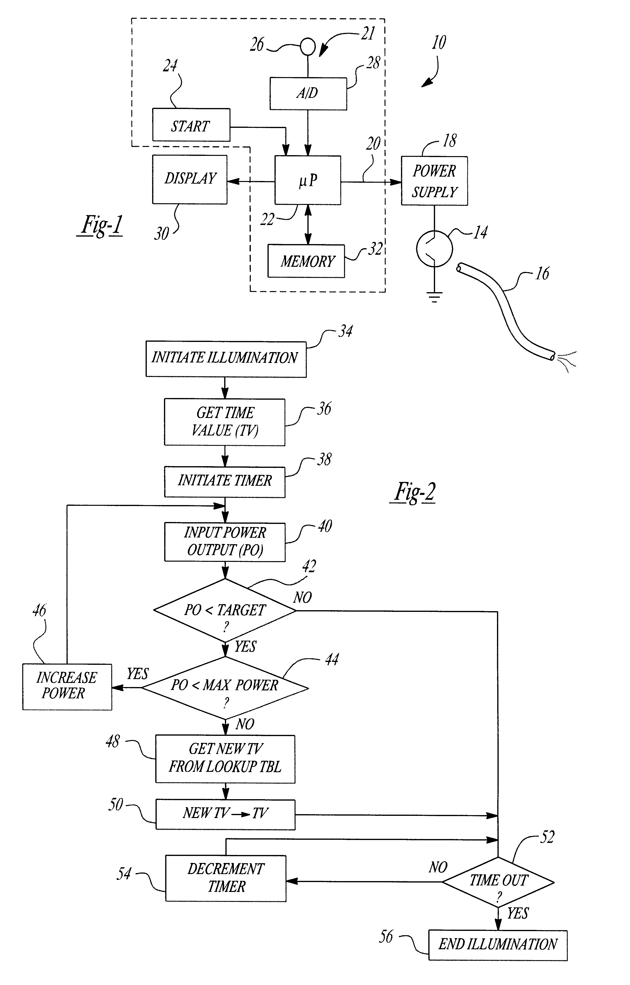
In the latter case, the microprocessor extends the duration of activation of the power supply, and thus extends the illumination of the light source, by an amount sufficient to achieve a predetermined amount of light energy from the light source. This predetermined amount of light energy is sufficient to completely cure the photohardenable material.
In the preferred embodiment, the microprocessor utilizes a lookup table stored in digital memory to determine the new time period for activation of the light source as a function of the power output signal from the photocell whenever the power supply is at its maximum current rating. The microprocessor also preferably outputs a signal to a display, such as an LED or a LCD display, representative of the time period required for complete cure of the photohardenable material. Such a display is helpful to the dentist to determine when it is economically desirable to replace the light source and thus reduce the cure time for the photohardenable material.

Problems solved by technology

In dentistry, it is oftentimes necessary to restore certain portions of the patient's teeth.
The primary disadvantage of argon lasers, however, is that they are very costly to obtain.
A still further disadvantage of the use of halogen lights is that such lights degradate over a period of time.
Since photohardenable materials require a minimum amount of energy in order to obtain a full cure, the use of an incandescent light for an insufficient time period may result in an inadequate cure of the photohardenable material.

Method used


Image

  • Curing system for photohardenable materials
  • Curing system for photohardenable materials

Examples


Embodiment Construction

With reference first to FIG. 1, a block diagrammatic view of the curing system 10 of the present invention is there shown. The curing system 10 includes a light source 14. Preferably, the light source 14 is a xenon arc light although other types of lights, such as a halogen light, may alternatively be used. Furthermore, any conventional delivery system, such as a fiberoptic 16, can be used to deliver the light output from the light source 14 to a target site.

A variable power output power supply 18 is electrically connected to the light source 14 so that, upon activation of the system 10, the power supply 18 provides electrical power to the light source 14 thus illuminating the light source 14. The power supply 18 is capable of providing a variable power up to a preset maximum amount in dependence upon a control signal on an input line 20 to the power supply 18. Typically, the power output from the power supply 18 varies as a function of the voltage value on its input line 20. Furthe...


PUM


Abstract

A curing system for a photohardenable material is disclosed having an electrically powered light source and a variable power supply electrically connected to the light source. During calibration, a photocell determines the power output of the light source and produces an output signal representative thereof. A control circuit then controls the illumination of the light source by the power supply. This control circuit includes a comparator which compares the power output signal from the photocell with a target value and then varies or increases the power from the power supply to the light source up to a maximum power output whenever the power output signal from the photocell is less than the target value. Following calibration, the control circuit also activates the power supply for a time period sufficient to obtain a substantially constant energy output from the light source per light activation. In the event that the power output signal is less than the target value and also that the power supply is at its maximum power output, the control circuit increases the duration of illumination of the light source beyond a preset time period by an amount sufficient to obtain a substantially constant energy output from the light source per activation.

Description

I. Field of the InventionThe present invention relates to a curing system for photohardenable materials of the type used in dental restoration work.II. Description of the Prior ArtIn dentistry, it is oftentimes necessary to restore certain portions of the patient's teeth. For example, such restoration may be required after removal of a cavity from the patient's teeth.Although gold, amalgam and other metals have been used for such restoration work in the past, in many situations it is more desirable to use a photohardenable material. Such photohardenable materials have a whitish color designed to match the patient's teeth. Thus, once the photohardenable material has been placed on the affected area of the patient's teeth and cured, the restoration becomes invisible or almost invisible, and is thus aesthetically more pleasing than the previously known use of gold and / or amalgam.There have been two previously known types of light sources used to cure photohardenable materials of the ty...

Claims


Application Information

Patent Timeline
IPC IPC(8): A61C13/00A61C13/15
CPCA61C19/003
Inventor PARKER, WILLIAM S.
Owner AMERICAN DENTAL TECH
Learn More