
Power generation method and power generating apparatus

Inactive Publication Date: 2001-10-09
MITSUBISHI HEAVY IND LTD
View PDF26 Cites 61 Cited by
  • Summary
  • Abstract
  • Description
  • Claims
  • Application Information

AI Technical Summary

Benefits of technology

Further, another object of the present invention is to provide a method by which the cost of a facility is low and exert little bad influence on the environment.
Furthermore, in accordance with the present invention, one of the various boiler-oriented fuels, which are utilized only in a boiler and are inexpensive and have low utilization factors and are pressed to be treated, and the gas-turbine-oriented fuels, which are easily obtained and are excessive and hardly produce toxicant that causes pollution, can be selected and used freely. Thus, further efficient power generation is achieved. Additionally, increase in ability of power generation can be attained by small-scale investment, because an additional partial-processing facility is unnecessary.

Problems solved by technology

However, in the case of the combined cycle power generation method using LNG, the storage of the fuel, namely, LNG costs very much, and a problem in supplying LNG may occur.
However, many troubles have occurred owing to impurities contained in crude oil and residue oil.
Further, it is pointed out that the maintenance cost has amounted up to a larger sum in comparison with that in the case of using light oil and LNG.
This results in drop of the melting point of metal used as the material of each blade of the gas turbine, and causes ash component to adhere to the blades.
Method of gasifying all of raw fuel has encountered the problems that excessive facilities are needed for pre-treatment of raw fuel, that a special type gasification furnace and a special type boiler to be combined with this gasification furnace are necessary, that operating conditions are severe, that as a result of gasifying all of the raw fuel, the quantity of the produced gas is large, that excessive facilities are needed for dust removal and purification of a gas, that the treatment of the remaining molten ash is needed, and that even a fuel to be used in a steam turbine is gasified and the obtained gas is purified.
This technique, however, has the problem in that ingredients, such as Na salt, K salt and V compound, which corrode the turbine blades, are frequently included in the gas, because the gasification temperature is not lower than 1000.degree. C., and thus there is the necessity for eliminating these ingredients.
This technique further has the problem in that because a system constituted by the combination of a gasification device, a gas turbine and a fluidized bed boiler is peculiar, the extensive adjustment of the facility is needed in applying this technique to a boiler provided with a radiation heat transfer surface and a convention heat transfer surface, such as the existing boiler / steam turbine system, and thus, practically, this technique is subject to the constraint that this technique can be applied for establishing a new facility.
This technique further has the problem in that the purification of the gas obtained at high temperature should be performed at low temperature and there is a great loss of energy, and that the cost of the entire facility becomes excessive.
Additionally, increase in ability of power generation can be attained by small-scale investment, because an additional partial-processing facility is unnecessary.
Conversely, the coal reserve is high, and the price thereof is low.
Moreover, there have been not known such a power generation facility and experimental equipment.
However, because the hydrogenation is an exthothermic reaction, a necessary amount of heat to be supplied to the apparatus is very small.
Moreover, the heat quantity of this distillate is high.
Thus, complete liquefaction is not necessarily performed.
Thus, the method and apparatus of the present invention become uneconomical in respect of the cost for equipment and processing.

Method used


Image

  • Power generation method and power generating apparatus
  • Power generation method and power generating apparatus
  • Power generation method and power generating apparatus

Examples


example a-1

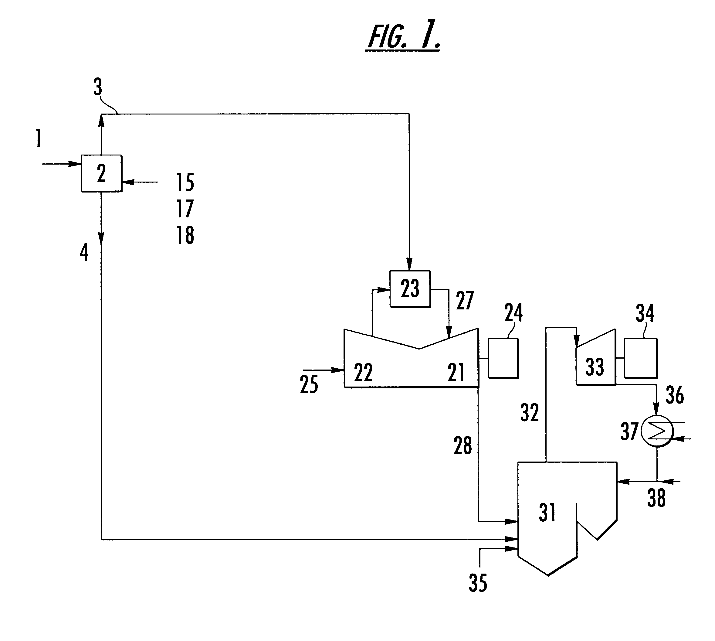
High-temperature carbonization of 1000 kg / hr of the following dried coal is performed at a temperature of about 1000.degree. C. by using the apparatus of FIG. 1. As a result, a distillate and coke are obtained.

Raw Material Coal (after dried)

Moisture Content: 2% by weight

Volatile Matter: 30% by weight

Fixed Carbon: 51% by weight

Ash: 17% by weight

Calorific Value: 5,780 kcal / kg

Coke

Production Rate: 550 kg / hr

Volatile Matter: 2% by weight

Fixed Coal: 67% by weight

Ash: 31% by weight

Calorific Value: 6,300 kcal / kg

Gas Component

Production Rate: 355 Nm.sup.3 / hr

Calorific Value: 5,050 kcal / Nm.sup.3

Oil Component

Production Rate: 57 kg / hr

Calorific Value: 9,100 kcal / kg

The aforementioned distillates (namely, the gas component and the oil component) are supplied to the gas turbine and are burned therein. The gas turbine exhaust gas is at a temperature of about 580.degree. C. and contains about 14% by volume of oxygen. The aforementioned residue (coke) can be burned by supplying the gas turbine exhaust g...

example a-2

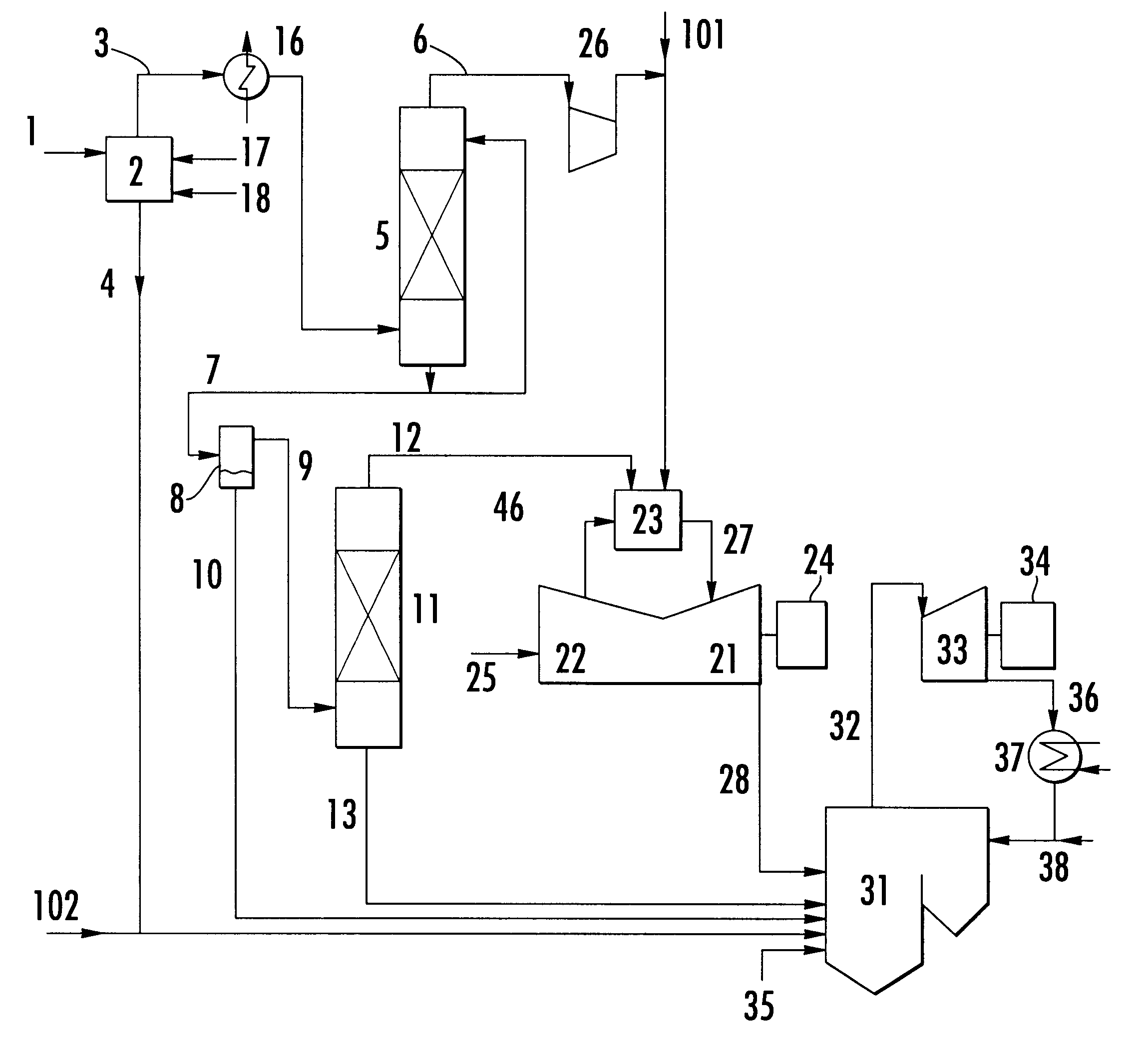
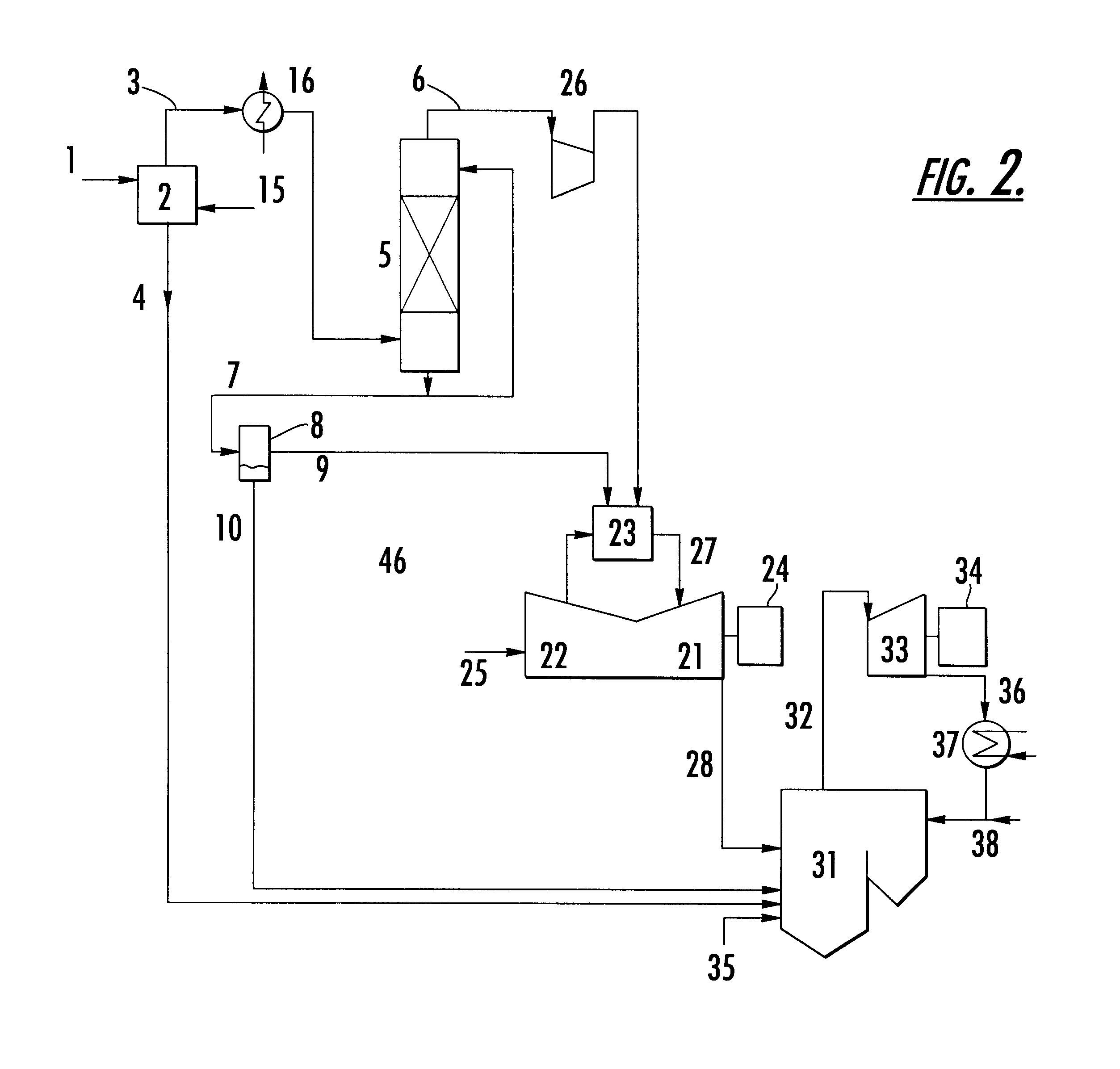
Low-temperature carbonization of 1,000 kg / hr of the following dried coal is performed at a temperature of about 600.degree. C. by using the apparatus of FIG. 2. As a result, a distillate and char are obtained. The distillate is cooled and washed by a liquid component. Further, a water layer is separated therefrom by the separating tank. Thus, a gas component and an oil component are obtained.

The gas component and the oil component are used as the gas turbine fuel. The coke and the separated water layer in the distillate are used as the boiler fuel.

Raw Material Coal (after dried)

Moisture Content: 4% by weight

Volatile Matter: 31% by weight

Fixed Carbon: 50% by weight

Ash: 15% by weight

Calorific Value: 6,430 kcal / kg

Char

Production Rate: 669 kg / hr

Volatile Matter: 11% by weight

Fixed Coal: 65% by weight

Ash: 24% by weight

Calorific Value: 6,200 kcal / kg

Gas Component

Production Rate: 180 Nm.sup.3 / hr

Calorific Value: 7,100 kcal / Nm.sup.3

Oil Component

Production Rate: 110 kg / hr

Calorific Value: 9,100 ...

example a-3

Thermal decomposition carbonization of the coal of Example A-2 is performed at a temperature of about 450.degree. C. by using the apparatus of FIG. 2. As a result, a distillate and a residue are obtained. The distillate is cooled and washed by a liquid component. Further, a water layer is separated therefrom by the separating tank. Thus, a gas component and an oil component are obtained.

The gas component and the oil component are used as the gas turbine fuel. The residue and the separated water layer are used as the boiler fuel. Then, these fuels are burned by supplying air. Sulfur content in each of the gas component and the liquid component is 0.52% by weight. Na content, K content and Vanadium content are 0.5 ppm by weight. Therefore, even when using such a gas turbine fuel, no corrosion of the turbine blade and so on occurs.


PUM


Abstract

A method and an apparatus for power generation, by which high-efficiency power generation is achieved by utilizing a boiler-oriented fuel such as inexpensive coal, heavy oil and waste plastic, and by further utilizing a gas-turbine-oriented fuel in some cases, without exerting bad effects on the environment, at low equipment cost. In the apparatus, first, the boiler-oriented fuel is separated into a distillate and a residue by partial processing. The distillate (in some cases, with a gas-turbine-oriented fuel) is supplied to a gas turbine to generate electric power. Further, a combustion exhaust gas discharged from the turbine is supplied to a boiler. Then, the residue (in some cases, with a boiler-oriented fuel) is burned to obtain steam. Further, electric power is generated by the steam.

Description

FIELD OF THE INVENTION AND RELATED ART STATEMENTThe present invention relates to a method and an apparatus for power generation, wherein a boiler-oriented fuel, such as coal and heavy oil is separated into a distillate and a residue by performing partial processing, and subsequently, a gas turbine fuel obtained from the distillate or a combination of the gas turbine fuel and another gas-turbine-oriented fuel is supplied to a gas turbine, the gas turbine fuel and the gas-turbine-oriented fuel are burned to generate electric power, on the other hand, a boiler fuel comprising the residue or a combination of the residue and the boiler-oriented-fuel and / or other boiler-oriented fuels are supplied to a boiler, these fuels are burned to generate steam, and power is generated by means of a steam turbine. The present invention further relates to a power generation method and apparatus for burning an exhaust gas again wherein an exhaust gas discharged from a gas turbine is supplied to a boile...

Claims


Application Information

Patent Timeline
IPC IPC(8): F01K23/06F02C3/26F02C3/28C10J3/46F01K23/10C10L1/00C10L3/00C10L5/00F02C6/00F02C6/18F02C7/22
CPCF01K23/064F01K23/067F02C3/28Y02E20/16Y02E20/18Y02T50/60F01K23/06
Inventor IIJIMA, MASAKI
Owner MITSUBISHI HEAVY IND LTD
Learn More