
Coupling system for the transfer of a confined planar object from a containment pod to an object processing unit

a technology of confined planar objects and coupling systems, which is applied in the direction of lighting and heating apparatus, lifting devices, chemical vapor deposition coatings, etc., can solve the problems of not being able to adapt to just-in-time production flexible use, additional difficulties, and inability to prevent mutual pollution of silicon wafers stored inside, so as to preserve the purity of the atmosphere in the box and inside the processing uni

Inactive Publication Date: 2001-08-14
COMMISSARIAT A LENERGIE ATOMIQUE ET AUX ENERGIES ALTERNATIVES
View PDF7 Cites 27 Cited by
  • Summary
  • Abstract
  • Description
  • Claims
  • Application Information

AI Technical Summary

Benefits of technology

The coupling is impervious to the surrounding medium. The cleanliness and purity of the atmosphere in the box and inside the processing unit are therefore preserved.

Problems solved by technology

The costs and technical difficulties connected with fitting out clean rooms of large volume that come under a high cleanliness category, have however led to the use of confined receptacles of small size able to contain the objects for which a clean environment is required.
Among the latter, mention may be made of the fact that they cannot prevent mutual pollution of the silicon wafers stored inside.
Also, on account of their fixed capacity, approximately 25 wafers, these interfaces are not adapted to flexible use for just-in-time production.
Additional difficulties arise when the wafers or flat objects must be maintained in a pure or inert atmosphere, for example a nitrogen atmosphere.
These difficulties are, for example, connected with the need to frequently drain the airlock whose inside volume is generally fairly considerable, on account of the presence of the transfer robot in particular.
Also, the confinement receptacles and the airlocks of the processing units do not generally enable transfer of the wafers in a vacuum.

Method used


Image

  • Coupling system for the transfer of a confined planar object from a containment pod to an object processing unit
  • Coupling system for the transfer of a confined planar object from a containment pod to an object processing unit
  • Coupling system for the transfer of a confined planar object from a containment pod to an object processing unit

Examples


Embodiment Construction

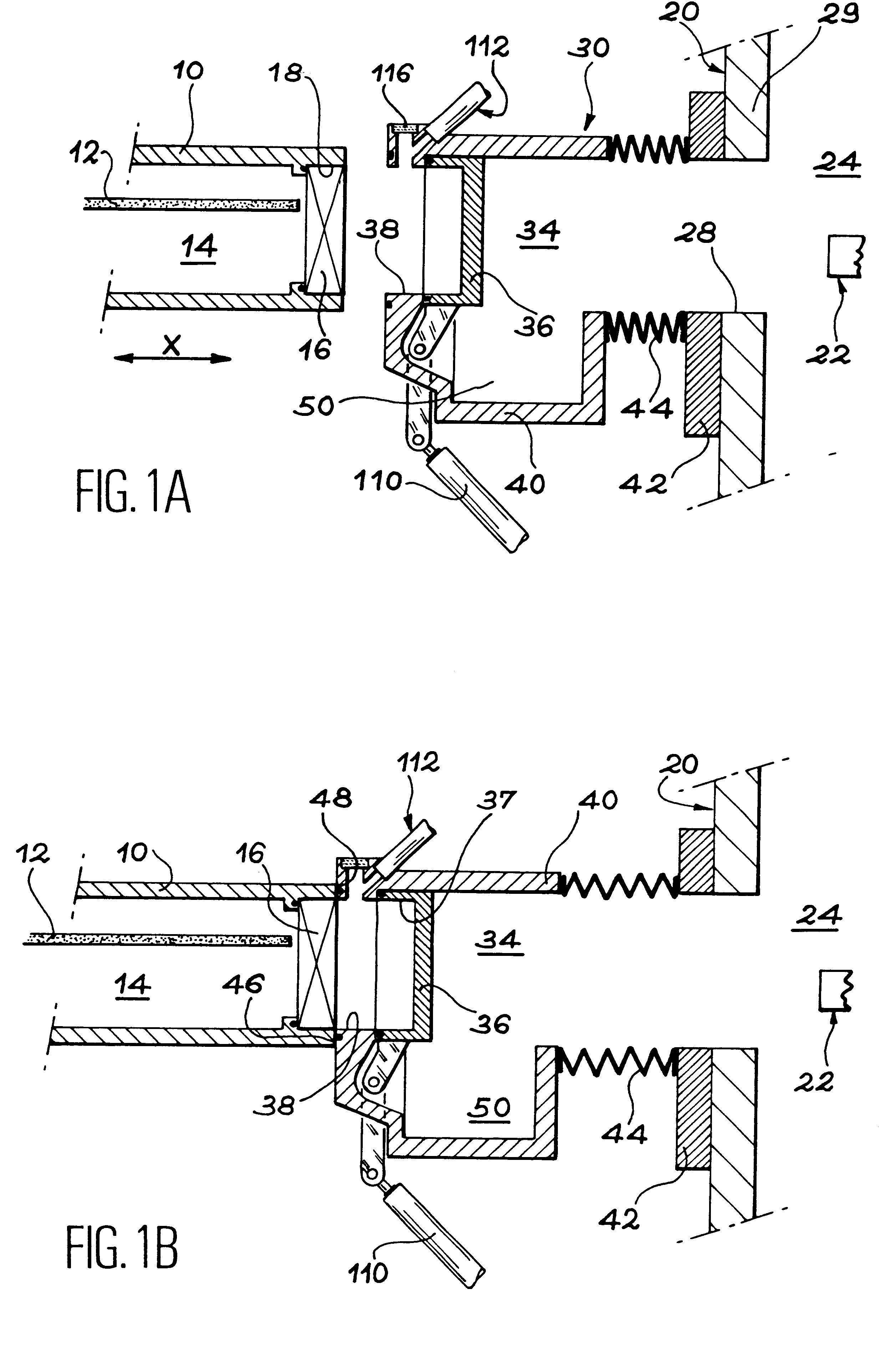
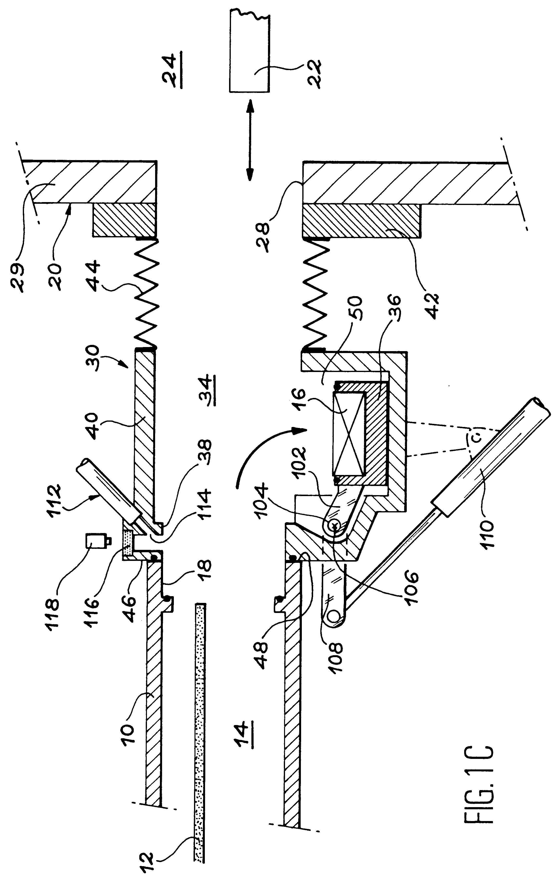
Essential elements of the transfer system and its operating principle are shown in FIGS. 1A to 1F which correspond to successive stages of a transfer operation. For better clarity, identical or similar elements in the different figures carry the same reference numbers.

In FIGS. 1A to 1F a confinement box, shown in part, is designated reference 10. It contains a flat object 12 such as a semiconductor wafer, for example. Flat object 12 is housed in the inner volume 14 of the box which encloses a clean, optionally pure, atmosphere, that is to say free from chemical contaminants.

A door 16 serves as a shutter for a side opening 18 in box 12 also called first opening. Door 16 closes the first opening in FIG. 1A.

Reference 20 designates a processing unit in which the flat object must undergo processing. This processing, when the flat object is a silicon wafer in particular, corresponds to the fabrication stages of electronic components. The processing may comprise depositing, etching, shapin...


PUM

PropertyMeasurementUnit
Timeaaaaaaaaaa
Shapeaaaaaaaaaa

Abstract

A coupling system for the transfer of a flat object from a confinement box towards a processing unit for processing the flat object. The coupling system includes a first shutter, at least one second opening, a second shutter, and a third shutter associated with the second opening on a side facing the processing unit, and devices for releasing the first, second and third shutter, after coupling the transfer opening of the confinement box with the transfer opening of the processing unit, in order to allow the transfer of the object between the confinement box and the processing unit.

Description

The present invention relates to a coupling system for confined transfer of a flat object from a confinement box towards a processing unit for the object.Said system may be used in particular for the transfer of silicon wafers placed individually in confinement boxes under controlled atmosphere, towards reactors such as chemical vapour deposition reactors or etching reactors, or plasma activated deposition reactors for example.By confined box under controlled atmosphere is meant a box whose inner medium has a determined composition, cleanliness, purity and / or pressure.START OF THE PRIOR ARTThe transfer of flat objects, in particular of silicon wafers, is generally conducted in a clean room directly from a stepped basket containing the flat objects towards the processing unit.The costs and technical difficulties connected with fitting out clean rooms of large volume that come under a high cleanliness category, have however led to the use of confined receptacles of small size able to ...

Claims


Application Information

Patent Timeline
IPC IPC(8): H01L21/67H01L21/00H01L21/677B65G49/00B65G49/07
CPCH01L21/67126H01L21/67748Y10S414/139
Inventor DOCHE, CLAUDE
Owner COMMISSARIAT A LENERGIE ATOMIQUE ET AUX ENERGIES ALTERNATIVES
Learn More