Eureka AIR delivers breakthrough ideas for toughest innovation challenges, trusted by R&D personnel around the world.

Pallet for combined surface mount and wave solder manufacture of printed ciruits

a combined surface mount and printed ciruit technology, applied in the manufacture of final products, non-printed masks,auxillary welding devices, etc., can solve problems such as falling off the board

Inactive Publication Date: 2001-07-31
CHUNG HENRY
View PDF7 Cites 39 Cited by
  • Summary
  • Abstract
  • Description
  • Claims
  • Application Information

AI Technical Summary

Benefits of technology

It is an object of the invention to provide a pallet that supports a double sided fab in a secondary reflow operation and prevents the components installed on one side of the fab during a first pick-and-place and reflow operation from dropping off the fab when the fab is turned over to perform the second reflow operation.
Another object is to provide a supporting pallet that is characterized by more uniform heat distribution during the reflow operation so that thinner PCBs (typically, 0.020" thick) can be manufactured that are not subject to intolerable warping.
minimizing heat loss from conduction of heat into the pallet by features of the invention that permit use of thinner material for the fab;
minimizing warpage of the fab and pallet holding the fab during the solder reflow step;
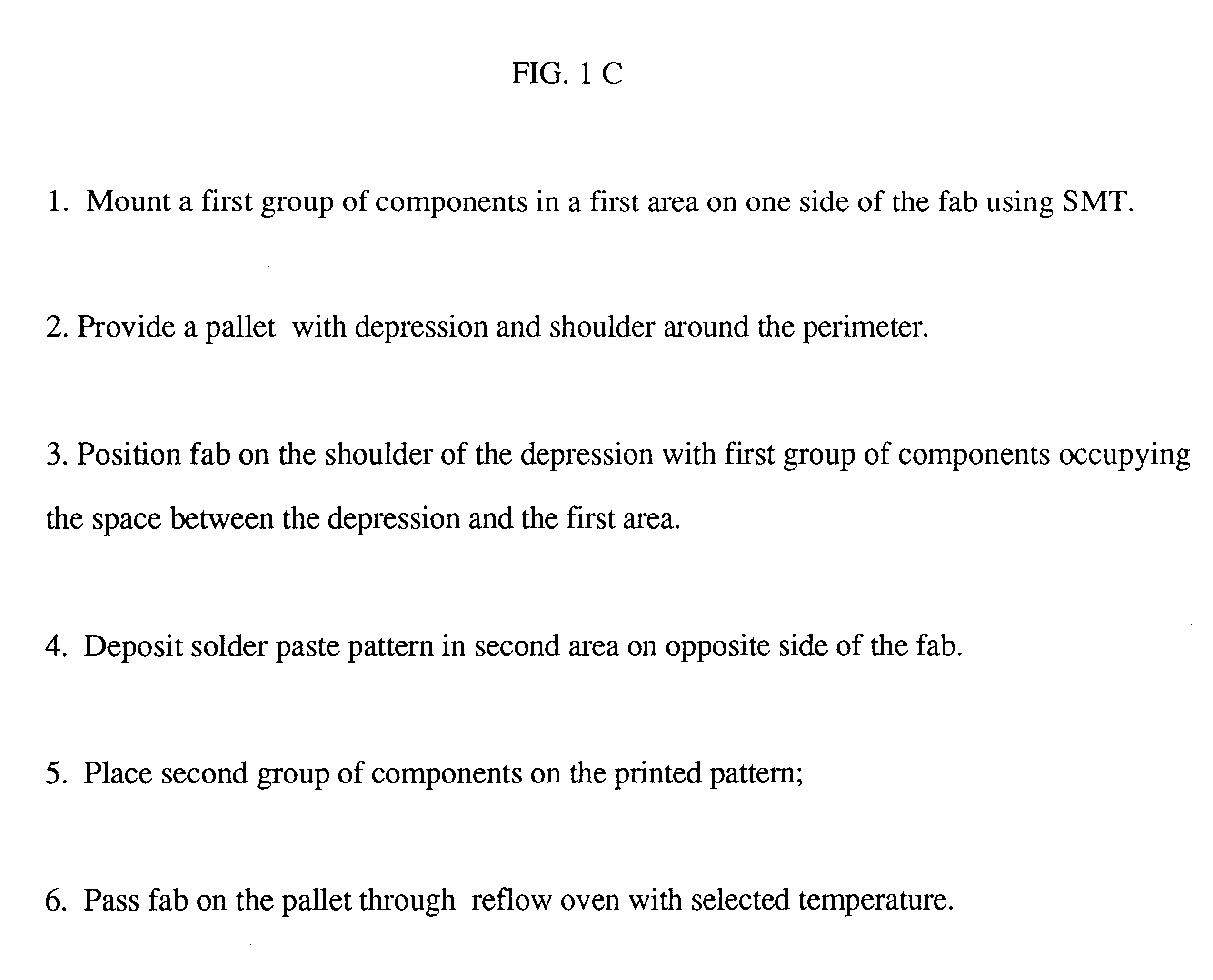
This invention is directed toward a pallet having a depression with a shoulder on at least two opposite sides of the depression so that a space is defined between the PCB supported on the shoulders and the surface of the depression. When the pallet supporting a PCB is placed in a solder reflow oven, the "down" side of the PCB (facing the depression) is shielded from the the direct heat of the oven, the surface temperature of the PCB facing the space is therefore less than temperature outside the space. In practice, power supplied to heat the oven is adjusted so that the temperature in the space is below the melting temperature of the solder paste applied to the PCB so that a first group of components mounted and soldered to the downside of the PCB will not fall off the PCB in a subsequent reflow step to secure a second group of components to the topside of the fab.

Problems solved by technology

The double sided PCB has the problem that, in a reflow operation, components soldered to one side of the board during a first reflow step can fall off the board when the board is turned over for the second reflow step.

Method used


Image

  • Pallet for combined surface mount and wave solder manufacture of printed ciruits
  • Pallet for combined surface mount and wave solder manufacture of printed ciruits
  • Pallet for combined surface mount and wave solder manufacture of printed ciruits

Examples


Embodiment Construction

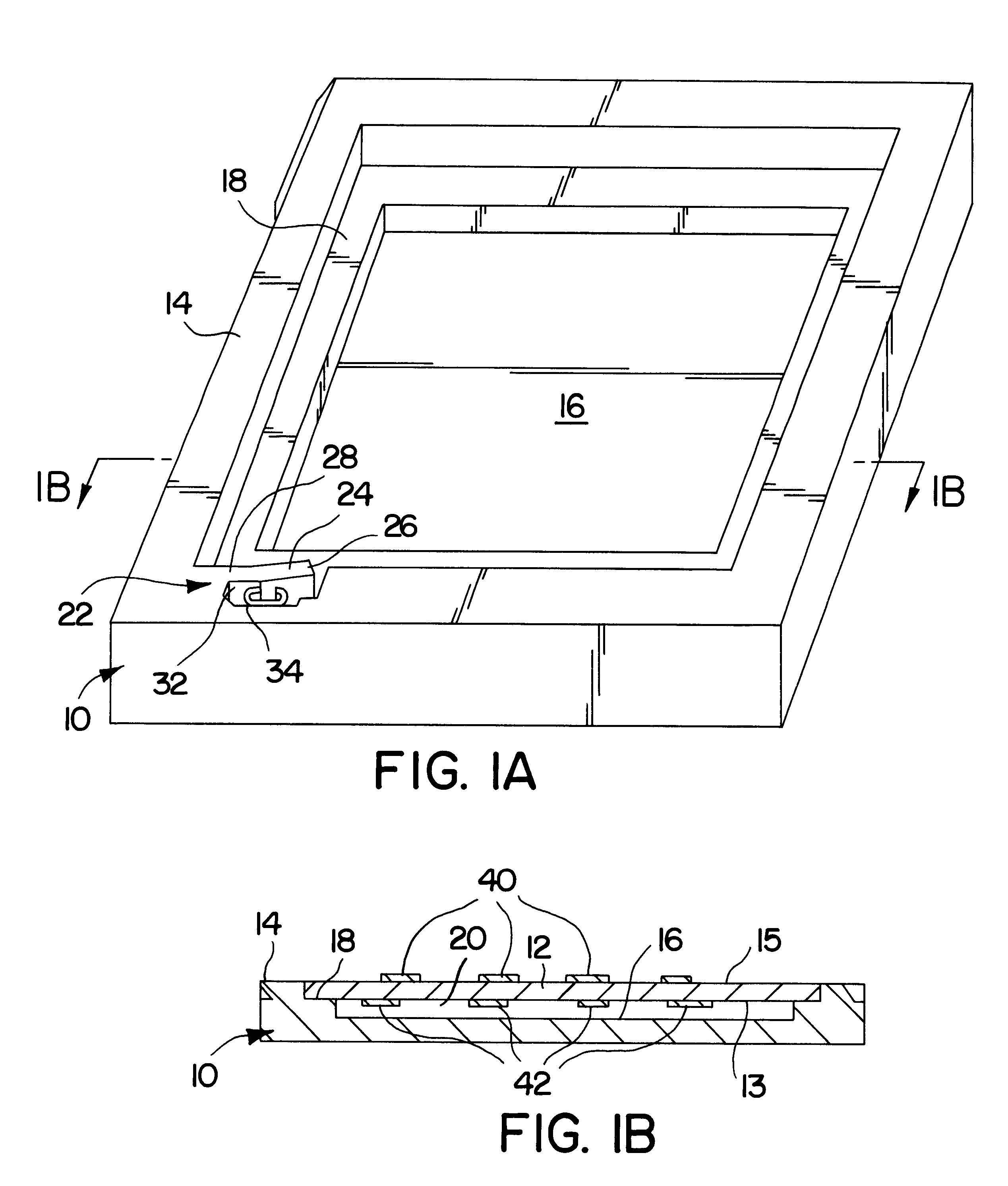
Turning now to a discussion of the drawings, FIG. 1A is a perspective view and FIG. 1B is a sectional view of a pallet 10 of one embodiment of this invention for supporting a fab 12 in a surface mount process that includes a print step, a pick and place step and a reflow step.

There is shown a pallet 10 (flat panel) being a rectangular outer frame 14 surrounding a depression 16. The depression has a shoulder 18 on its perimeter. As shown in FIG. 1B, the depression 16 is dimensioned so that the shoulder 18 supports a fab 12 and a space 20 is defined between the fab 12 (PCB) and the surface of the depression 16. The depth of the shoulder equals the thickness of the fab so that the top surface of the fab is coplanar with the top surface of the frame area of the fab.

A clamp 22 is formed in the frame against the side of the depression 16 for securing the fab on the pallet 14. There is shown a finger 24 formed by cutting out a portion of the frame 14 at the edge of the depression 16. The f...


PUM


Abstract

A pallet for mounting components on a double sided PCB including a fab (panel) having a frame area surrounding a depression. A shoulder around the depression is dimensioned to support the fab. The fab is laid on the shoulder with the a group of components mounted in a previous reflow operation in the space between the depression and a first area of the fab. The print, pick and place and reflow operations are performed to mount a second group of components on the opposite side of the fab. The first area of the fab is shielded from the heat of the oven so that the first components do not separate from the fab during the second reflow step. Standoffs in the depression prevent sagging of the board. Another area of the pallet has a recessed area with cutouts for wave soldering components located on the third area of the fab.

Description

This invention relates to apparatus for assembling components on printed circuit boards (PCB) and particularly to a fixture that supports the double sided PCB through surface mount technology (SMT) and wave solder processes.BACKGROUND AND INFORMATION DISCLOSUREThe technology for manufacturing circuits comprising components mounted on printed circuit boards has evolved continuously during the past fifty years keeping pace with the evolution of discrete semiconductor devices to present high density integrated circuits.The current "surface mount technology" (SMT) is applied to printed circuit boards (PCB) that have a plurality of layers of wiring with contact points from each layer extending up to "pads" located on the top and bottom surfaces of the board. Components are soldered to the pads.The process starts with a bare board referred to as a fab which has been manufactured with layered wiring and surface art comprising exposed pads. The fab is loaded into the printing machine utiliz...

Claims


Application Information

Patent Timeline
IPC IPC(8): B25B11/02B25B11/00B23K3/08B25B5/14B23K3/00B25B5/00H05K3/34
CPCB23K3/08B25B5/142B25B11/02H05K3/3415H05K3/3468B23K2201/42H05K3/3447H05K2203/304H05K2203/0173H05K2203/0557H05K2203/1476H05K2203/1572H05K2203/1581H05K3/3452B23K2101/42Y02P70/50
Inventor CHUNG, HENRY
Owner CHUNG HENRY
Why Eureka
Eureka Blog
Learn More