
Multi-facet concentrator of solar setup for irradiating the objects placed in a target plane with solar light

a concentrator and solar energy technology, applied in the field of solar energy technology, can solve the problems of high material consumption, large weight, complex technical problem,

Inactive Publication Date: 2001-05-01
ALLIANCE FOR SUSTAINABLE ENERGY
View PDF6 Cites 50 Cited by
  • Summary
  • Abstract
  • Description
  • Claims
  • Application Information

AI Technical Summary

Benefits of technology

Therefore, it is an object of the present invention to provide an apparatus for the accelerated testing of materials.
It is yet another object of the invention to provide an apparatus which allows one to attain concentration ratios up to a factor of approximately 100.
It is a further object of the invention to provide spectral characteristics of irradiating light flux as close to the UV portion of the natural sunlight spectrum of interest as possible. It is a further object of the invention to decrease the effect of excessive heating of objects under testing due to absorption of natural sunlight in its visible and infrared parts of spectrum, while observing that the share of this fraction comprises about 90% of the total flux intensity of natural sunlight.
The invention allows the achievement of required result which consists in a reduction of a time period necessary for testing the objects by a factor of up to 100 (several days instead of several months or years) with highly reliable predictability of behavior of objects under a wide variety of testing conditions due to creation of concentrated, uniform, and selective with respect to spectrum light spot in a plane wherein the samples under tests are arranged.

Problems solved by technology

At present, the simulation of irradiation conditions, particularly the simulation of multiple concentrations of radiation in combination with a set of different atmospheric factors which affect the samples, represents a complex technical problem.
However, high materials consumption and, consequently, large weight, complex kinematics of the Sun tracking, and impossibility to attain high concentration ratios (of the order of 100) of solar radiation are obvious disadvantages of this design.
However, the design of this concentrator is also characterized by complex Sun tracking and impossibility of obtaining high solar concentration ratios.
The design of this concentrator has an important disadvantage in that an increase in concentration ratio can be achieved also only by application of complicated kinematics of rotating samples in a target plane.

Method used


Image

  • Multi-facet concentrator of solar setup for irradiating the objects placed in a target plane with solar light
  • Multi-facet concentrator of solar setup for irradiating the objects placed in a target plane with solar light
  • Multi-facet concentrator of solar setup for irradiating the objects placed in a target plane with solar light

Examples


Embodiment Construction

The present example relates to the realization of the invention.

FIG. 3 shows the photo of the experimental setup with the multi-facet selective concentrator intended for accelerated natural sunlight weathering of materials.

FIGS. 4 and 5 demonstrate experimental data on reflective characteristics of the concentrator facets and distribution of flux power over a target area, respectively.

While the present invention has been described and illustrated in detail, it is clearly understood that the same is by way of illustration and example only and is not to be taken by way of limitation, the spirit and scope of the present invention being limited only by the terms of the appended claims. For example, the present invention can be also effectively used in a series of other applications such as the part of solar setups for waste waters detoxification, disinfecting and purification of water, laser pumping with natural sunlight radiation, targeted photo and photocatalytic synthesis of chemical...


PUM


Abstract

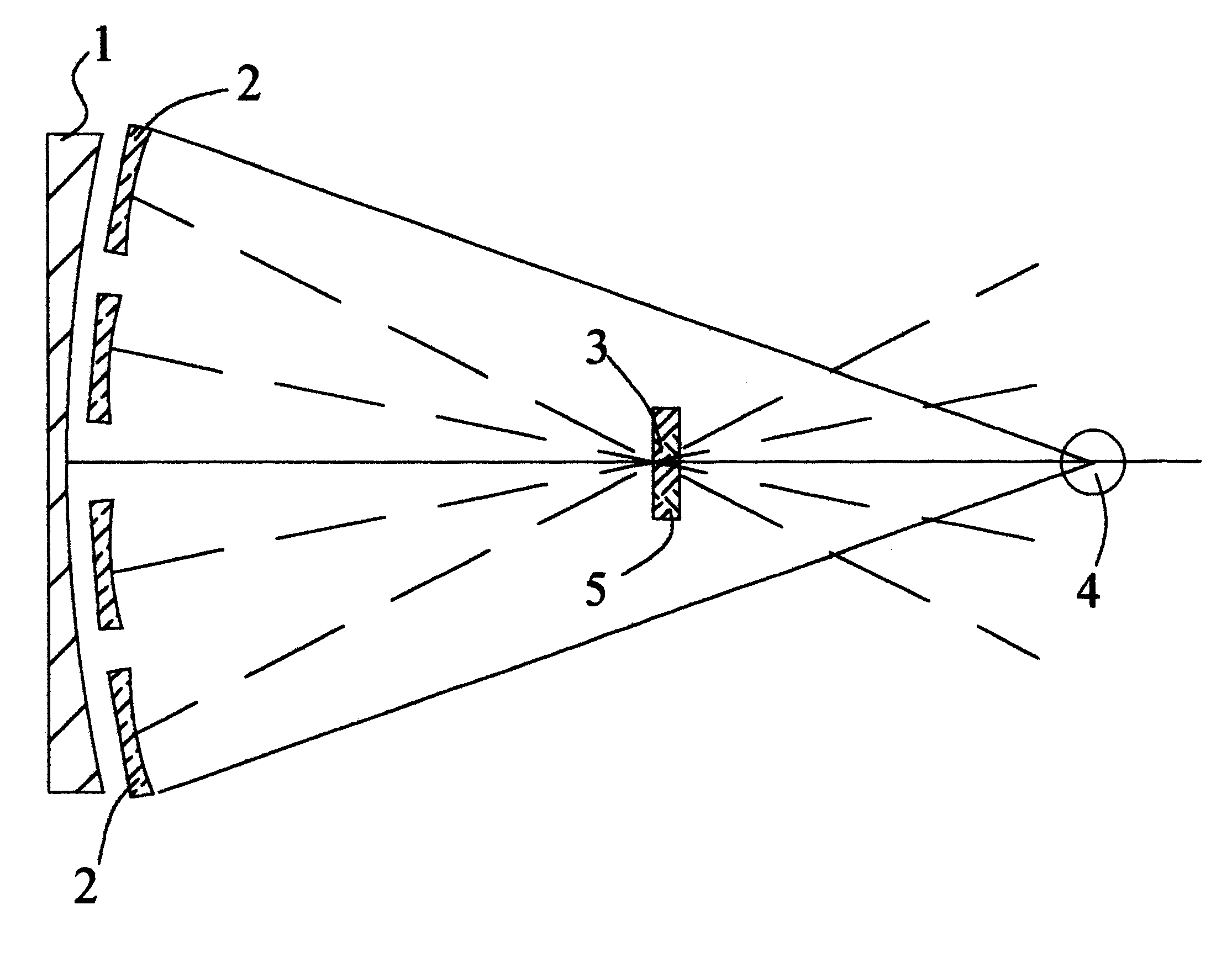
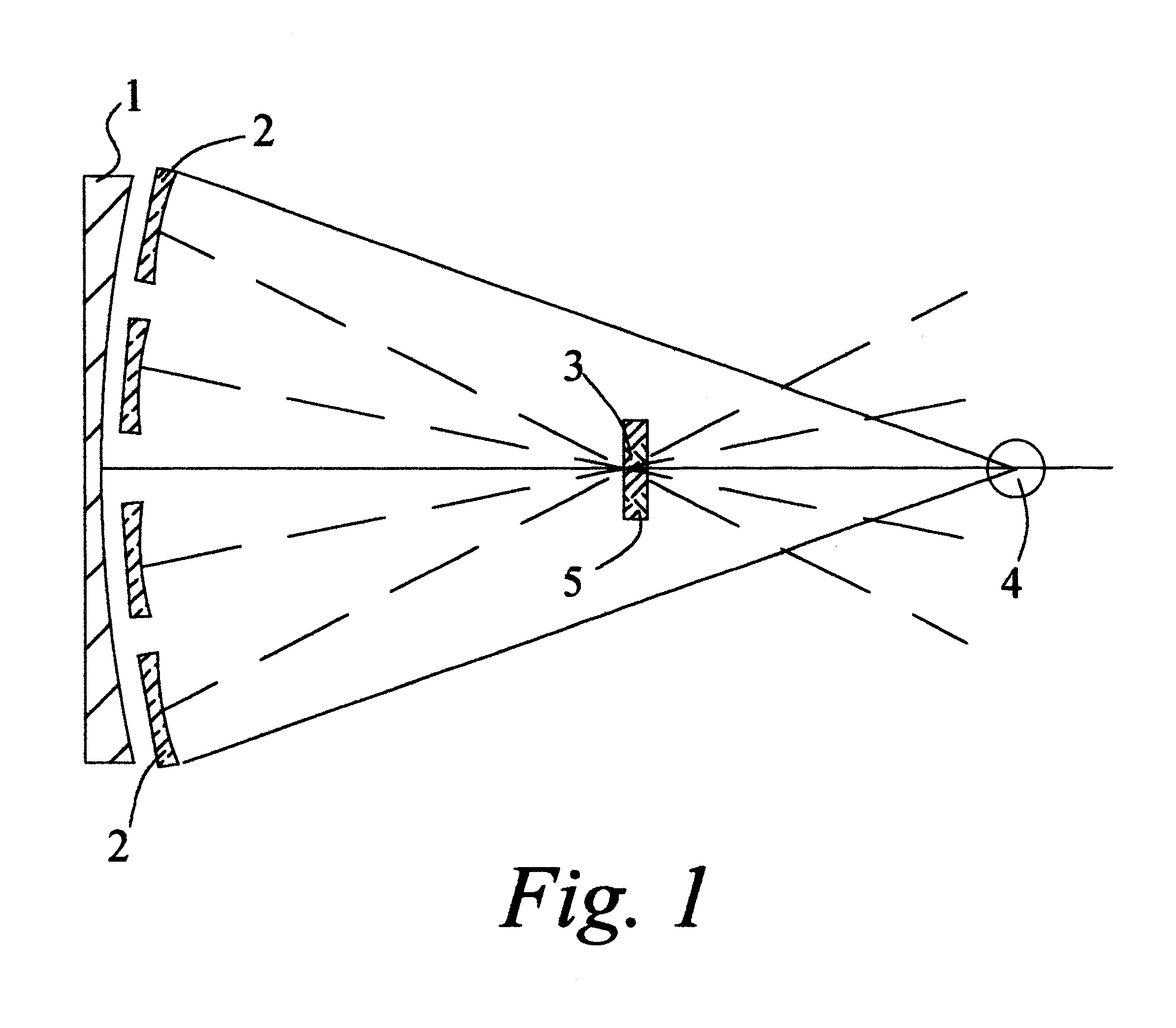
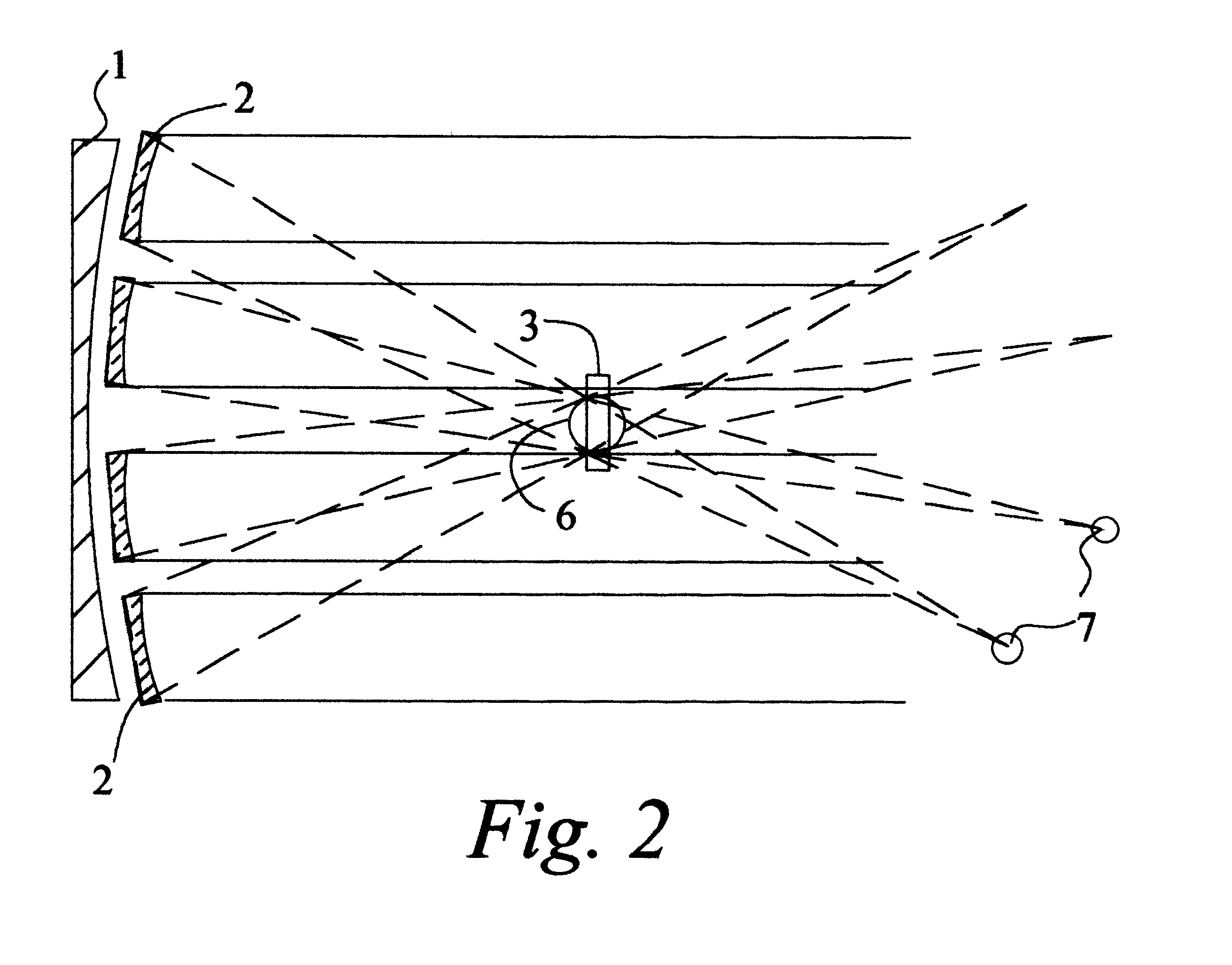
According to the proposed invention, this technical result is achieved so that many-facet concentrator of a solar setup for exposure of objects, placed in a target plane, to the action of solar radiation containing a supporting frame and facets differing by that the facets of the concentrator are chosen with spherical focusing reflective surfaces of equal focal lengths and with selective coatings reflecting a desired spectral fraction of solar radiation, and are arranged on the supporting frame symmetrically with respect to the common axis of the concentrator, their optical axes being directed to the single point on the optical axis of the concentrator located before the nominal focus point of the concentrator and determining the position of arranging the target plane.

Description

1. Field of the InventionThis invention relates to solar energy technology and, in particular, to the testing of materials and articles for resistance to solar light and weather factors with the use of concentrated solar radiation.2. Description of the Prior ArtThe combined action of atmosphere and solar radiation causes irreversible changes (degradation and natural aging) in various materials and articles. The most typical and important (with respect to technical and economic factors) examples of such changes are manifested as changes in the color of construction and finishing of materials, paints and varnishes, textile dyes (known as fading or discoloration), and degradation of mechanical characteristics of polymeric materials which can be demonstrated as the effect of embrittlement and destruction of polyethylene films used in hothouses after only one or two seasons.The rate of these and other degradation processes depends on the composition of the atmosphere, temperature, and ex...

Claims


Application Information

Patent Timeline
Patent Type & Authority Patents(United States)
IPC IPC(8): H01L31/052F24S23/70H01L31/054
CPCF24J2/10H01L31/0547Y02B10/20Y02E10/52Y02E10/40F24S23/70
Inventor LEWANDOWSKI, ALLAN A.YAMPOLSKIY, VLADISLAVALEKSEEV, VALERIESON, VALENTIN
Owner ALLIANCE FOR SUSTAINABLE ENERGY
Learn More