
Method for estimating a tire wear life

a tire wear life and tire technology, applied in vehicle tyre testing, roads, instruments, etc., can solve the problems of reducing the time required for testing, wasting a lot of time, and wasting a long time to estimate the tire wear li

Inactive Publication Date: 2001-04-10
BRIDGESTONE CORP
View PDF12 Cites 18 Cited by
  • Summary
  • Abstract
  • Description
  • Claims
  • Application Information

AI Technical Summary

Problems solved by technology

However, this method has a drawback in that the test is quite time-consuming because the distance to be driven by the vehicle for the test must be great in order to get an accurate measurement of the amount of wear of the tire required for a highly precise estimation.
However, the technology described in the specification of JP-B 1-56374 has a drawback in that at least one actual road test must be conducted for a long time and thus it still takes a long time to estimate the tire wear life, although the time required for the test can be decreased in comparison with the time required for methods of estimation using only one pair of tires in one run of the road test.
Therefore, this method has a drawback in that the accuracy of the estimation of the amount of wear is poor when a tire is mounted on a vehicle which is different from the vehicle used in the test or when a tire is used in an area whose environment is different from the environment of the test.
However, accurately estimating the wear life of a tire mounted on a vehicle in actual use is difficult when the factors taken into consideration are limited to these parameters.
Therefore, in the actual driving condition of a vehicle which is affected by so many diverse factors, it is obviously difficult to accurately estimate the wear of a tire using Schallamach's formula of the amount of wear in which only rigidities in the direction of driving, in the direction of braking and in the transverse direction are considered.

Method used


Image

  • Method for estimating a tire wear life
  • Method for estimating a tire wear life
  • Method for estimating a tire wear life

Examples


first embodiment

[The First Embodiment]

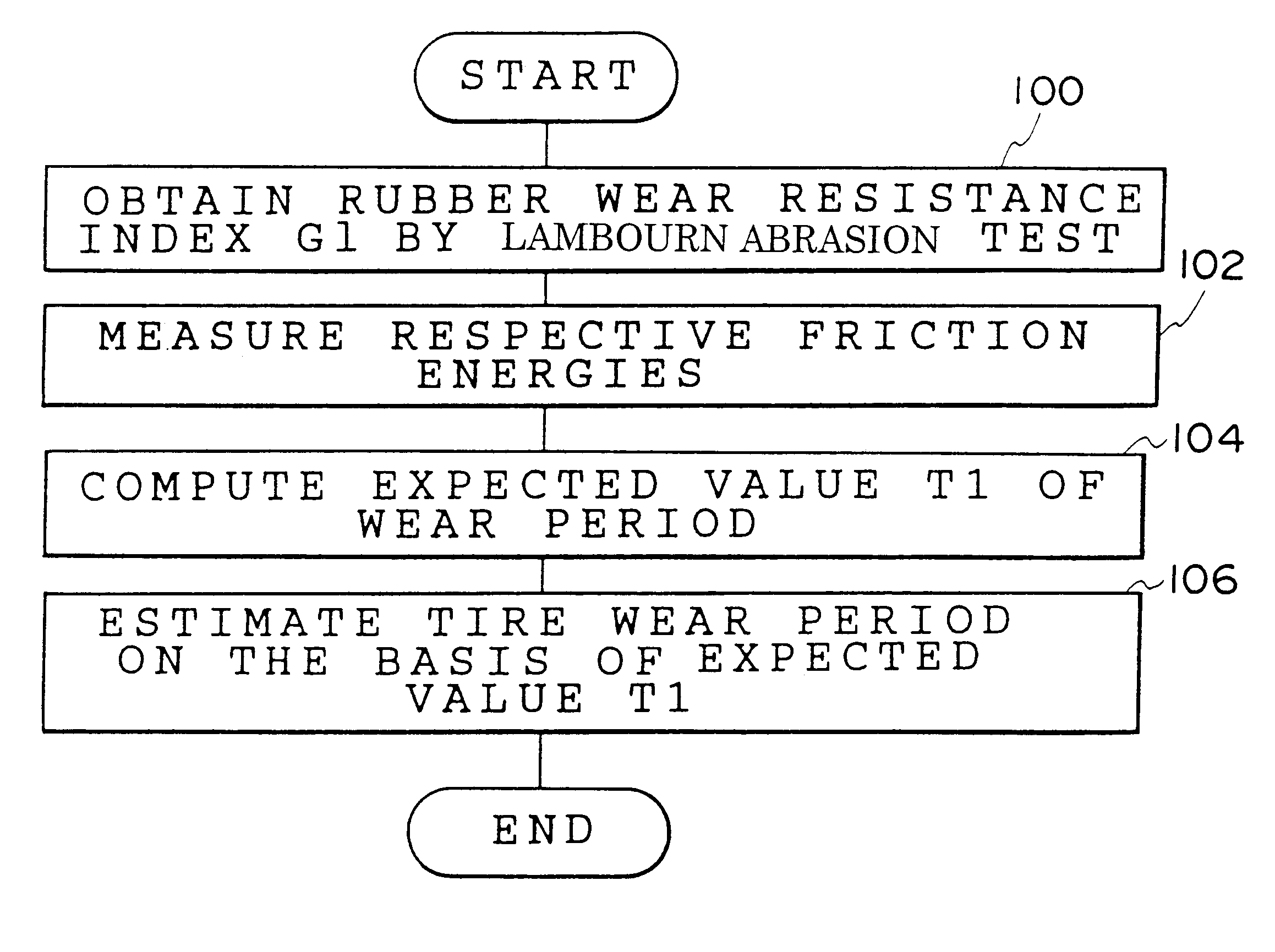
The first embodiment of the method for estimating a tire wear life of the present invention will be described with reference to the flow chart shown in FIG. 4.

In step 100, the wear resistance index G1 of a rubber sample which is made of the same material as the material used in the tire tread portion of a tire whose wear life is to be estimated (for example, a tire having a size 225 / 55R16) is obtained at a standard temperature of the atmosphere (for example, 25.degree. C.) in accordance with the Lambourn abrasion test specified in Japanese Industrial Standard K 6264.

In the next step 102, the friction energy of the tire Ewf in free rolling, the friction energy of the tire Ewa in a state in which the tire is imparted with a toe angle, the friction energy of the tire Ews in a state in which a side force is applied to the tire, the friction energy of the tire Ewd in a state in which a driving force is applied to the tire and the friction energy of the tire Ewb in a...

second embodiment

[The Second Embodiment]

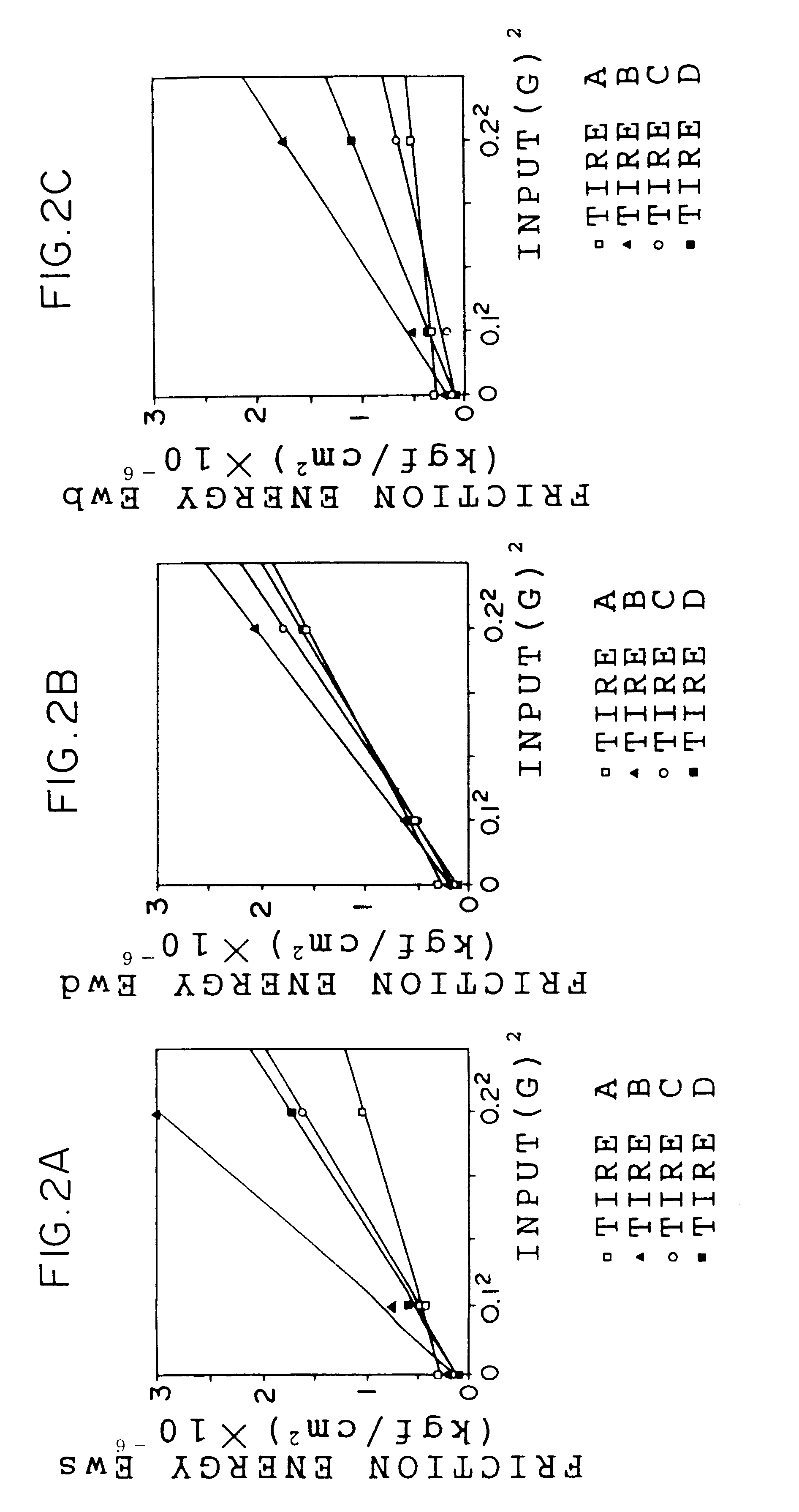
The second embodiment of the present invention will be described in the following. The present embodiment is different from the first embodiment described above in that the friction energy of the tire Ews under application of a side force, the friction energy of the tire Ewd under application of a driving force and the friction energy of the tire Ewb under application of the braking force, which are measured by using the apparatus 10 shown in FIG. 5 in the first embodiment, are obtained as data reflecting input forces in the actual use of the tire in the present embodiment.

The method for obtaining the friction energy of the tire Ews under application of a side force, the friction energy of the tire Ewd under application of a driving force and the friction energy of the tire Ewb under application of the braking force in the present embodiment will be described with reference to the flow chart shown in FIG. 6.

In step 200, using an input force in a transverse dir...

third embodiment

[The Third Embodiment]

The third embodiment of the present invention is described in the following. In the present embodiment, the toe angle, the camber angle and the load per one tire in the static and dynamic conditions of the vehicle to which the tire to be estimated is fitted are taken into consideration and this the friction energy Ew reflecting input forces in the actual use of the vehicle is calculated, allowing more accurate estimation of the tire wear life.

The method for estimating a tire wear life of the present embodiment will be described with reference to the flow charts shown in FIG. 8 and FIG. 9A in the following.

In step 300, data of the vehicle to which the tire whose wear life is to be estimated is fitted, are input. Such data include static properties (the toe angle, the camber angle and the load per one tire under the static condition) and dynamic properties (the toe angle, the camber angle and the load per one tire under the dynamic condition).

It should be noted t...


PUM


Abstract

A wear resistance index G1 of a tire whose wear life is to be estimated is measured by the Lambourn abrasion tester. Then, friction energies in free rolling, when the tire is fitted with a toe angle, under application of a side force, under application of a braking force and under application of a driving force of the tire are measured. An expected value of the wear life T1 is calculated using the wear resistance index G1 and the friction energies thus obtained and the wear life of the tire is estimated on the basis of the expected value of the wear life T1. The wear life of a tire can be estimated accurately in a short time in accordance with the method for estimating a tire wear life of the present invention.

Description

The present invention relates to a method for estimating a tire wear life, and more particularly, to a method for estimating a tire wear life which enables accurately estimating the tire wear life in actual use.DESCRIPTION OF THE RELATED ARTHeretofore, the wear life of a tire used for vehicles has been estimated from the condition of wear (the degree of wear or the amount of wear) after a vehicle on which the tire whose wear life is to be estimated is mounted is actually driven for a specific distance.However, this method has a drawback in that the test is quite time-consuming because the distance to be driven by the vehicle for the test must be great in order to get an accurate measurement of the amount of wear of the tire required for a highly precise estimation.To overcome the above drawback, in the technology disclosed in Japanese Patent Application Publication (hereinafter, referred to as JP-B) 1-56374, at least two pairs of test tires are mounted on a vehicle used for the test...

Claims


Application Information

Patent Timeline
IPC IPC(8): G01M17/02G01N3/56
CPCG01M17/02
Inventor SHIMIZU, AKIYOSHIYAMAGISHI, NAOTOMOURI, HIROSHISASAKA, NAOHIROKOBAYASHI, HIROSHIHARAGUCHI, TETSUNORIKATOH, KOHSHI
Owner BRIDGESTONE CORP
Learn More