
Molybdenum disilicide heating element and its production method

a technology of molybdenum disilicide and heating element, which is applied in the direction of ohmic resistance heating, electric heating, basic electric elements, etc., can solve the problems of dramatically reducing the heat capacity of the heat treatment furnace, unsatisfactory user experience, and the life of the mosi.sub.2 heating element, so as to achieve the effect of prolonging the life of the heating elemen

Inactive Publication Date: 2001-04-03
RIKEN CO LTD
View PDF9 Cites 28 Cited by
  • Summary
  • Abstract
  • Description
  • Claims
  • Application Information

AI Technical Summary

Benefits of technology

It is, therefore, an object of the present invention to provide a molybdenum-disilicide based ceramic composite heating element, in which the low-temperature oxidation of MoSi.sub.2 is prevented to satisfactorily prolong the life of the heating element used for the low-temperature heating, such as in a heat-treatment furnace for producing semiconductor.
The present inventors considered that the main reason for the pest phenomenon resides in the fact that, when the MoO.sub.3 is formed in the grain boundaries of MoSi.sub.2, an intergranular fracture (a separation of grains) occurred. The present inventors then designed the following molybdenum-disilicide based ceramic composite. According to the conventional measure for preventing the pest phenomenon, a dense and stable protective SiO.sub.2 film is formed on the surface of sintered material. According to the present invention, this measure is applied microscopically to the grain boundaries, so as to decrease the area of the grain boundaries, where the MoSi.sub.2 grains are in contact with one another, to as low a level as possible. The resultant material is a composite of MoSi.sub.2 and a silica-bearing oxide phase or a glass phase, which phase has a relatively low melting point as compared with the MoSi.sub.2 Such composite has a micro-structure such that as much as possible of the silica-bearing oxide phase or the glass phase is existing at the grain boundaries of the MoSi.sub.2 grains, thereby preventing the "pest" oxidation.

Problems solved by technology

Furthermore, by means of using the molybdenum-disilicide heating element and omitting a liner tube, which is usually made of silicon carbide and installed inside the heating element and the heat capacity of the heat treatment furnace is dramatically decreased.
Under the present situation, the life of the MoSi.sub.2 heating element is, therefore, unsatisfactory for the users.
The effects attained by this film are, however, not yet wholly satisfactory.

Method used


Image

  • Molybdenum disilicide heating element and its production method
  • Molybdenum disilicide heating element and its production method
  • Molybdenum disilicide heating element and its production method

Examples


examples 3-6

The MoSi.sub.2 used had 1.7 .mu.m of average particle diameter. The MoSi.sub.2 used contained as impurities 0.006 mass % of Fe, 0.001 mass % or less of Cu, 0.008 mass % of Al, 0.001 mass % or less of Ca, 0.001 mass % or less of Mg, 0.005% or less of Na and 0.001 mass % or less of K. The clay mineral used was artificial (synthesized) Sumectite clay, which contained as impurities 0.005 mass % of Fe.sub.2 O.sub.3, 3.98 mass % of Na.sub.2 O, and 0.02 mass % of K (trade name--Sumecton SA, produced by Kunimine Industries Co., Ltd.). MoB, which was also used, had 2.6 .mu.m of average particle diameter, and contained as impurities 0.01 mass % of Fe and 0.001 mass % of Cu. The MoSi.sub.2, clay mineral and MoB were blended in the proportions shown in Table 2. The rod-shaped sintered materials having 3 mm and 6 mm in diameter were produced by the method of Example 2. The treatment for removing Na was then carried out at 1500.degree. C. for 5 hours, while evacuating the furnace interior to redu...

examples 7 , 8

Examples 7, 8

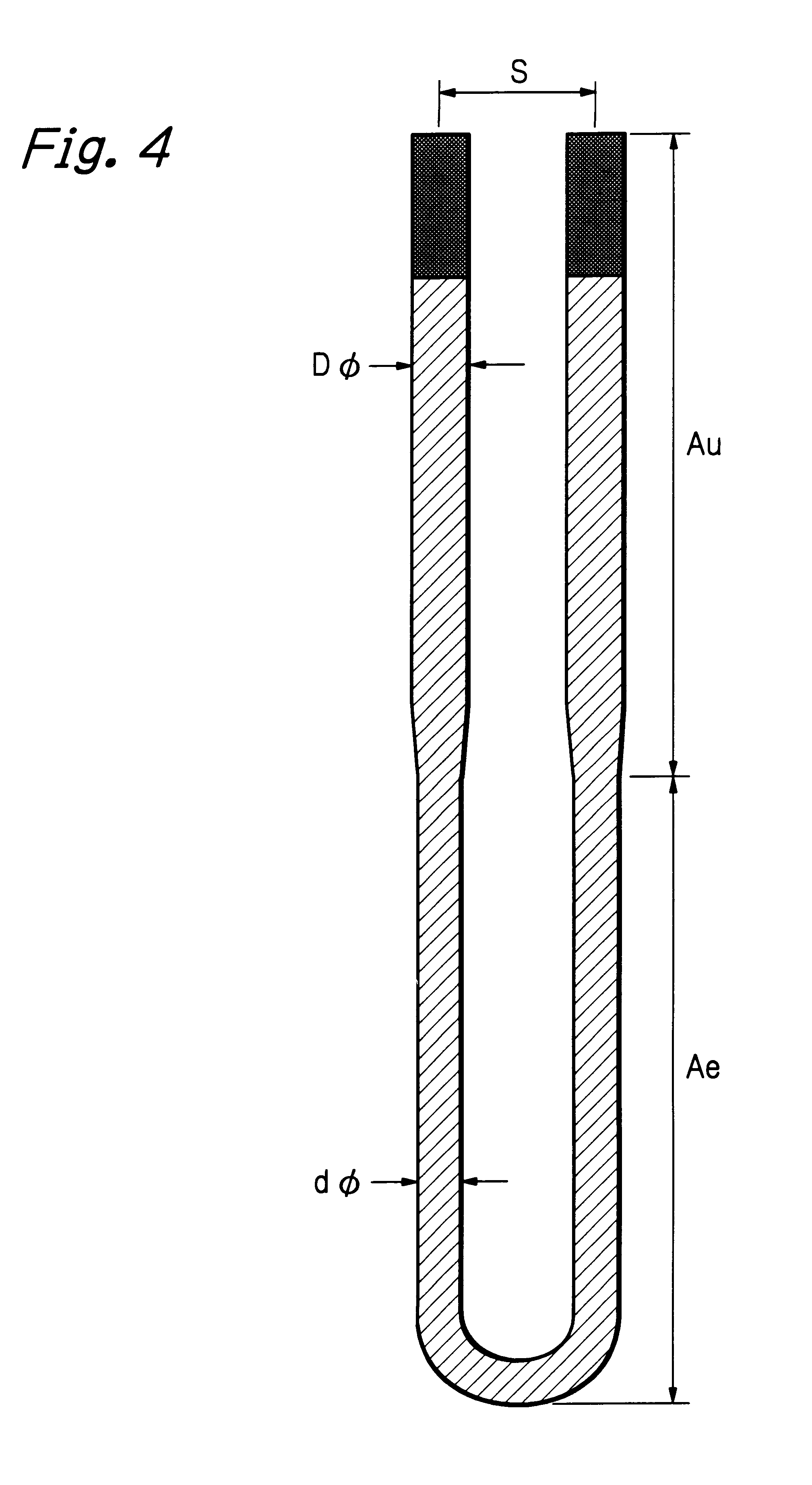
The MoSi.sub.2 used in Example 1 was also used in these examples. The synthesized kaolinte (product of Toyo Denka Co., Ltd.) additionally used in these examples had 45.9 m.sup.2 / g of specific surface area, and contained as impurities 0.09 mass % of Fe.sub.2 O.sub.3, 0.06 mass % of Na.sub.2 O and 0.01 mass % of K.sub.2 O. The MoSi.sub.2 and the synthesized kaolinite were blended in the proportions shown in Table 3. The U-shaped heating elements were produced by the method of Example 1 and the same tests as in Example 1 were carried out.

examples 13 and 14

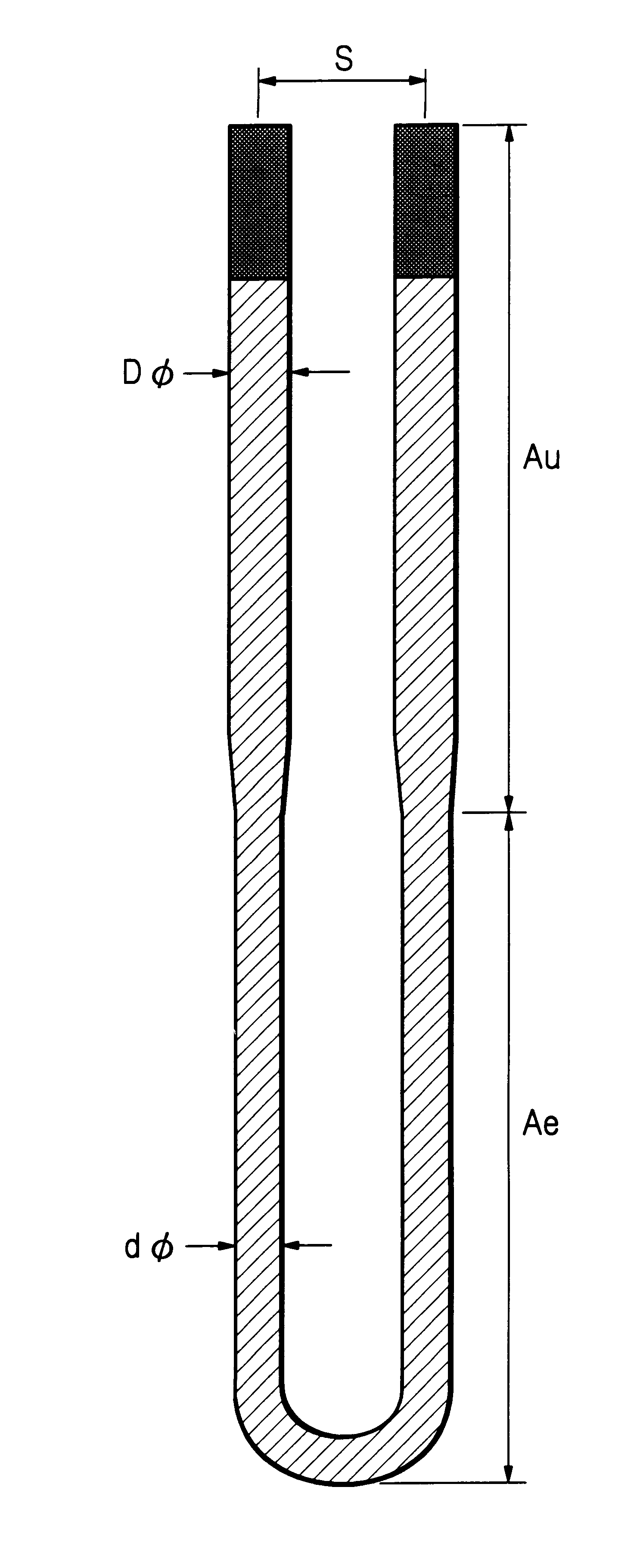
The material of Example 3 and the material of Example 10 were used to produce the meander-type multi-shank heating element as shown in FIG. 9. Two kinds of meander-type multi-shank heating elements were produced using rods of 3 mm in diameter. One element had forty (40) shanks with the shank pitch (d) of 15 mm and the shank length of 120 mm. The other had thirty two (32) shanks with the shank pitch (d) of 20 mm and the shank length of 260 mm. The 40-shank elements were mounted on the top and bottom zones and the 32-shank elements were mounted on the center zones of a semi-cylindrical insulating mould of 200 mm in inner radius and 950 mm in length. The insulating mould was made of ceramic fiber. A pair of semi-cylindrical mould, on which the four meander-type multi-shank heating elements were mounted as described above, were combined to form the heating element module in a tubular form and mounted in a batch-type heating furnace. In FIG. 9, "n" means a number of shanks.

The performanc...


PUM

PropertyMeasurementUnit
temperatureaaaaaaaaaa
average particle diameteraaaaaaaaaa

Abstract

The MoSi2 heating element has not been so resistant under the low-temperature heating, because the low-temperature oxidation, which is attributable to the grain boundary oxidation, occurred. In the present invention, long life under the low-temperature heating is attained by the following two structures. (1) The MoSi2 grains have a network structure and are linked three dimensionally. (2) The secondary, silica-bearing oxide or glass phase forms a net-like structure around the MoSi2 grains.

Description

BACKGROUND OF INVENTION1. Field of InventionThe present invention is related to a molybdenum disilicide (MoSi.sub.2) based ceramic composite heating element, more particularly to the heating element of a heat-treatment furnace, in which severe temperature-distribution is required, such as an oxidation, diffusion or low-pressure chemical-vapor-deposition (LP-CVD) furnace for producing semiconductors. In addition, the present invention is related to a production method of the molybdenum-disilicide based ceramic composite heating element.2. Description of Related ArtHeretofore, an Fe--Cr--Al based, metallic heating element has been used in a heat-treatment furnace for producing semi-conductors, such as an oxidizing, diffusion or LP-CVD furnace. In a recent development of the rapid thermal processing, which pursues micro-devices and enhances cost competence in the production of semiconductor devices, the MoSi.sub.2 heating element has been used. That is, since the heat resistance of the...

Claims


Application Information

Patent Timeline
Patent Type & Authority Patents(United States)
IPC IPC(8): C04B35/58C04B35/80H05B3/14
CPCC04B35/58092C04B35/806H05B3/148H05B2203/018C04B35/80
Inventor UCHIYAMA, TETSUOJIANG, WAN
Owner RIKEN CO LTD
Learn More