Eureka AIR delivers breakthrough ideas for toughest innovation challenges, trusted by R&D personnel around the world.

Method and apparatus for debugging, verifying and validating computer software

a computer software and verification method technology, applied in the computer field, can solve the problems of time-consuming and costly debugging process, and the process of verifying the operation of software under all operating modes is typically a very time-consuming and costly effor

Inactive Publication Date: 2001-01-09
MCDONNELL DOUGLAS
View PDF5 Cites 111 Cited by
  • Summary
  • Abstract
  • Description
  • Claims
  • Application Information

AI Technical Summary

Problems solved by technology

Although the process of debugging has been automated to some extent through the use of error codes and commercial debuggers for popular development languages, the process of debugging remains a very time consuming and costly part of the software development process.
The process of verifying the operation of software under all operational modes is typically a very time-consuming and costly effort, in which all possible scenarios are executed for the software, to identify its response under all conditions.

Method used


Image

  • Method and apparatus for debugging, verifying and validating computer software
  • Method and apparatus for debugging, verifying and validating computer software
  • Method and apparatus for debugging, verifying and validating computer software

Examples


Embodiment Construction

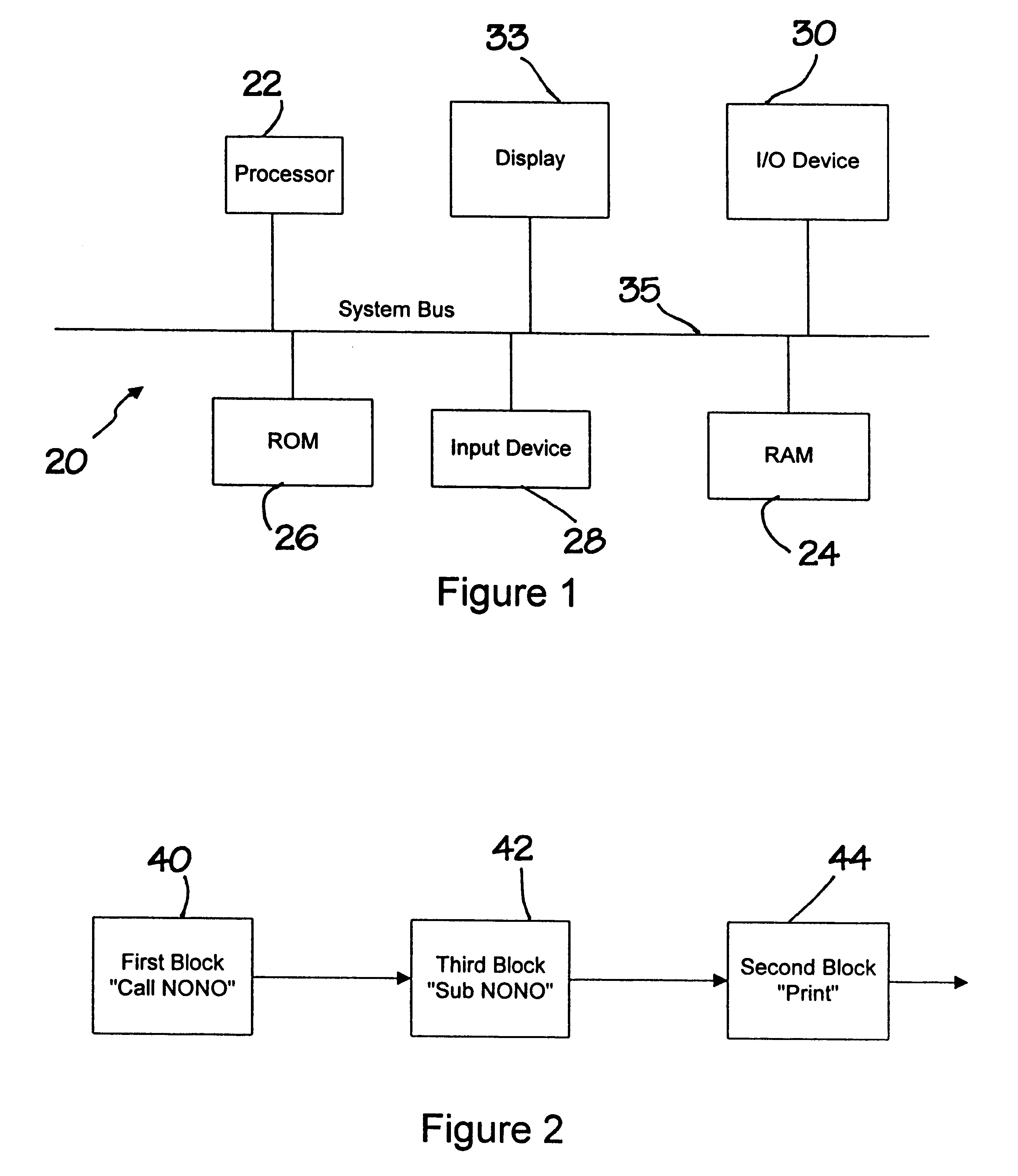
Referring more particularly to the drawings, FIG. 1 illustrates a computer system 20 comprising a microprocessor 22, a Random Access Memory (RAM) 24 and a Read Only Memory (ROM) 26. The computer system 20 of the presently preferred embodiment further comprises an input device 28, such as a keyboard, and Input / Output (I / O) device 30 which may be connected to a printer, for example, and a display 33. A system bus 35 interconnects the various components. Other components and buses (not shown) may be connected to the system bus 35 for providing additional functionality and processing capabilities. A network access device may be included, for example, for providing the computer system 20 access to an Internet, intranet or other network system. The computer system 20 of the present invention is configured to implement and / or facilitate the implementation of all of the below-described processes, which are described in connection with FIGS. 2-10.

In accordance with the present invention, the...


PUM


Abstract

A new approach for software debugging, verification and validation is disclosed. The present invention utilizes a knowledge-based reasoning approach to build a functional model of the software code for identifying and isolating failures in the software code. The knowledge-based reasoning approach of the present invention uses the software design, which is preferably based upon a flow chart or block diagram representation of the software functionality, to build the functional model. The software block diagram contributes to the functional model by defining the inputs and outputs of the various blocks of code, as well as defining data interconnections between the various blocks of code. In accordance with a method of the present invention, test points are strategically inserted throughout the code, and each test point is associated with a corresponding block of code. Expected values of the test points for an expected proper-operation execution of the computer program are generated. The computer program is then executed on a computer, and the actual values of the test points from the program execution are compared with the expected values of the test points. Failed test points which do not agree with corresponding expected values are determined. The functional model, which includes information functionally relating the various test points to one another, is then used to isolate the failed test points to one or more sources of failure in the code.

Description

1. Field of the InventionThe present invention relates generally to computers and, more particularly, to computer software debugging, verifying and validating devices and techniques.2. Description of Related ArtThe process of correcting developmental errors within computer software code is commonly referred to as debugging. A typical debugging procedure entails a software designer executing the prototype software and attempting to determine which portions of the code are responsible for incorrect operation. The software developer typically examines a failure within the software code and attempts to determine the portion, module or line of software code that is responsible for the failure.Conventional debugging techniques include steps of inserting output statements after subsections of code to notify the developer of the results either before, during or after the execution of the remainder of the program. By incorporating output statements into the code, the developer can more quick...

Claims


Application Information

Patent Timeline
IPC IPC(8): G06F11/36
CPCG06F11/3608G06F11/3672
Inventor DARTY, MARK A.
Owner MCDONNELL DOUGLAS
Why Eureka
Eureka Blog
Learn More