Dosing and discharging device for flowable media including powder/air dispersions

Inactive Publication Date: 2000-05-02
ING ERICH PHEIFFER GMBH & CO KG
View PDF39 Cites 48 Cited by
  • Summary
  • Abstract
  • Description
  • Claims
  • Application Information

AI Technical Summary

Benefits of technology

The object of the invention is to create a dosing device of the aforementioned type in which it is possible to use a simple dosing device independent of the nature of production or preparation of the medium to be discharged.
Gravity offers the simplest possibility for creating the force operating in opposition to the action produced by the flow. Gravity reversal, due to the buoyancy of the valve body, could also be used under corresponding conditions. It would also be possible to use springs or other forces, for example magnetic force, as the force directed counter to the flow action. During dosage, as a result of the flow action, the valve body is placed in motion, preferably with a force action dependent on the speed of flow. As a result, in the case of different flow rates, dosing takes place in a very uniform manner, i.e. with lower flow rates it will last longer until the closure stops the dosage, whereas dosing is terminated earlier with higher flow rates. In all cases it is possible to effectively ensure that no uncontrolled quantity can be dispensed.
The closure characteristics can be modified by various factors. Thus, the shape and absolute weight, as well as the specific gravity of the closure body can influence the characteristics in the same way as its relationship to the channel in which movement occurs. Thus, for example, the diameter of the channel in which the closure body moves may change to attain a desired dosing characteristic. Thus, it is possible through a relatively high force (high weight or additional loading) to maintain the rest for the closure body until a pressure suitable for producing an adequate flow has built up. A relatively large annular space is provided for flow around the valve body, so as to obtain an adequate time lag and the annular space for flow around the valve body is then reduced in cross section along the length of the channel. This assures the transfer into the closure position under all circumstances and also brings about a certain throttling prior to the end of dosing, so that the latter does not occur too suddenly. This more particularly applies in the case if, as is preferred, the dosing device is used as an inhaler, where the flow takes place by oral suction via a mouthpiece.

Problems solved by technology

The body can be movable through the length of a path, which movement produces a time delay.

Method used


Image

  • Dosing and discharging device for flowable media including powder/air dispersions
  • Dosing and discharging device for flowable media including powder/air dispersions
  • Dosing and discharging device for flowable media including powder/air dispersions

Examples


Embodiment Construction

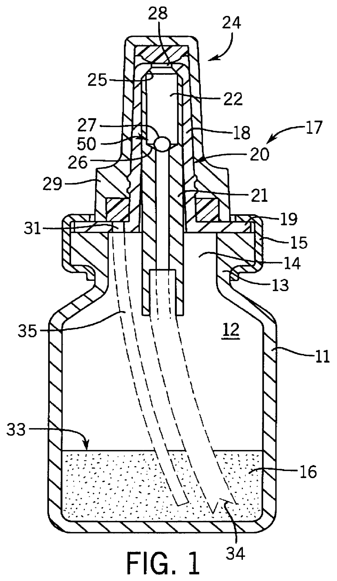
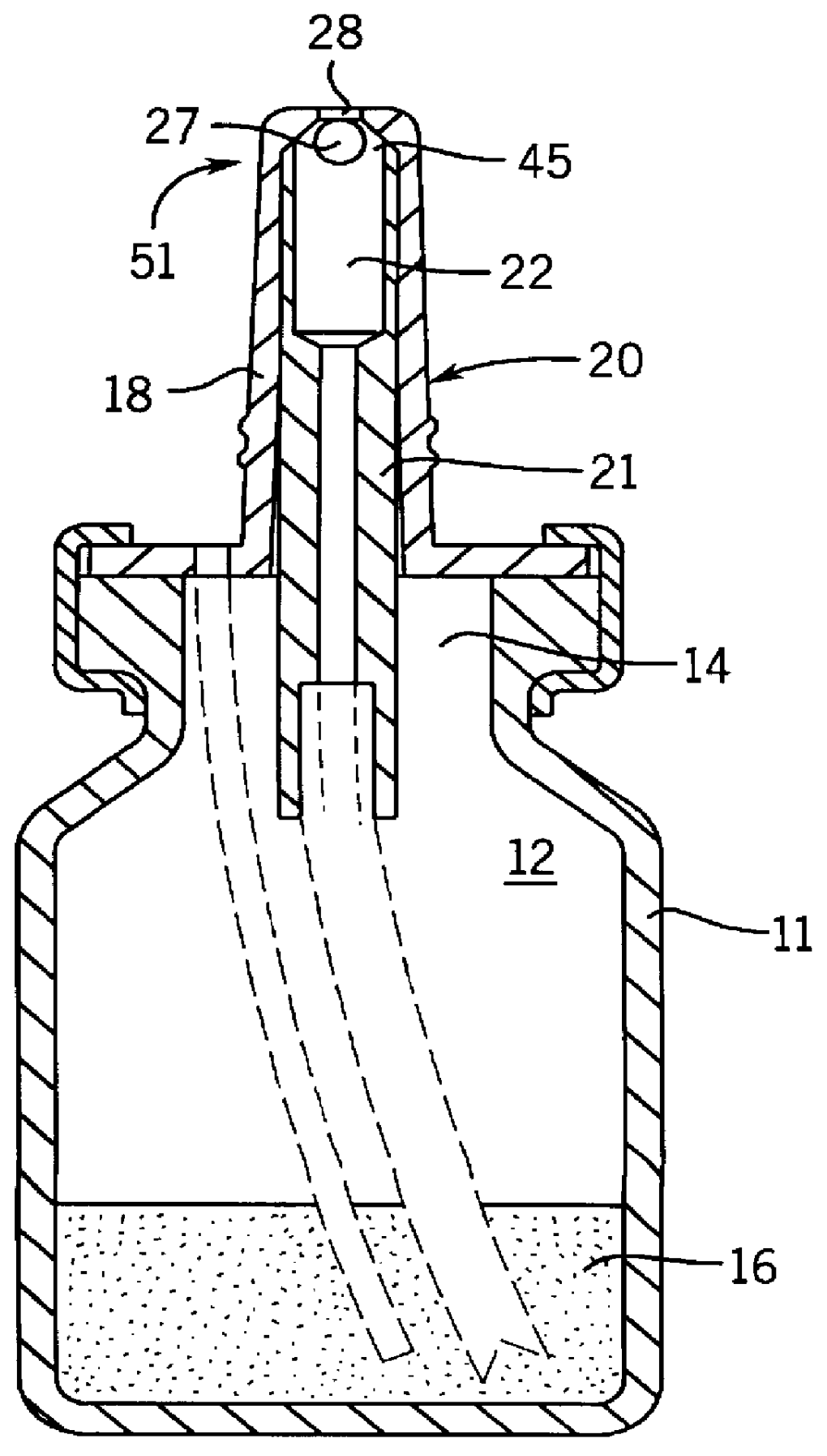
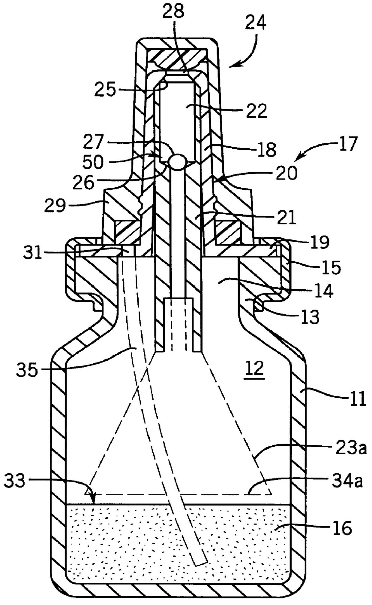
FIGS. 1 and 2 show a dosing device 17 fitted to a container 11, in whose interior 12 is provided a supply of a powder 16, by means of a crimped closure 15, which engages over a flange 19 of the dosing device casing 20. The container can be a normal bottle with a neck 13 and an opening 14, but other container configurations are also possible.

The dosing device 17 has a mouthpiece 18 extending upward from the flange 19, for insertion into a body opening, such as a nostril or the mouth, to exert a suction action. At its upper end mouthpiece 18 has an aperture 28, at which terminates a discharge channel 22, which is located in an insert 21, which is pressed into the casing 20.

At its upper end close to the aperture 28, the casing forms a valve seat 25 of a closure 24. The discharge channel has over a considerable distance of its length a diameter which is larger than the ball 27, so that a flow space having a cross-section 45 surrounding the valve body 27 is formed. At the end of the wide...


PUM


Abstract

A dosing device (17) for the medical administration of powder (16) through the nose or mouth has a valve body (27) which is movable in a discharge channel (22) between two valve seats (25, 26). During suction, the spherical valve body (27) is raised from the lower, container-sealing valve seat (26) and moved by a flow drag to the upper valve seat (25), so that it closes the discharge channel (22) and terminates dosing. The formation of the air / powder dispersion can be assisted in that the air subsequently sucked into the container is directed onto or into a powder supply or to a powder receiver in a pre-chamber fillable by tilting the device for pre-dosing.

Description

FIELD OF USE AND PRIOR ARTThe invention relates to a dosing device for flowable media, particularly in discharge apparatuses for pharmaceutical or cosmetic products, such a powder / air dispersions, the medium flowing through a discharge channel, which has a closure.For the administration of pharmaceuticals dosing always constitutes a significant problem. The action of a product is often dependent on, or is at least improved when, administration takes place in aerosol form. Atomization takes place in air for liquid products or, with solids, in the form of a solid aerosol or a corresponding dispersion of a powder in air. Such dispersions or aerosols can be produced by discharging with pumps, it being possible in the case of liquid products to introduce the liquid directly in a finely atomized form into the ambient air, i.e. not to use the air as an atomizing medium. This is more difficult with powders, where dosing is particularly problematical.Powder atomizing devices are known (DE 41...

Claims


Application Information

Patent Timeline
IPC IPC(8): A61M15/00B05B11/06B05B11/00A61J7/00A61M16/00
CPCA61M15/0065B05B11/062B05B11/0021A61M2202/064B05B11/00444
Inventor FUCHS, KARL-HEINZ
Owner ING ERICH PHEIFFER GMBH & CO KG
Why Eureka
Try Eureka