Non-postural change two feet braking for roller skates

a technology of non-postural change and roller skates, applied in the direction of brake systems, vehicle components, braking element arrangements, etc., can solve the problems of not being able to achieve the effect of effective braking of the gross weight of the skater under acceleration or even deceleration, all lost its commercial goals, and not being able to allow intermittent application of brakes

Inactive Publication Date: 2000-04-25
INTENGAN FRANKLIN SANCHEZ
View PDF8 Cites 3 Cited by
  • Summary
  • Abstract
  • Description
  • Claims
  • Application Information

AI Technical Summary

Benefits of technology

It is finally an object of the present invention to include a brake system that can be intermittently and incrimentally operated at will as the skating condition requires.
A roller skate is provided including a boot and a base consisting of front portion and rear portion connected by concave mediate portion. Preferably, the base front and rear portions should lie in conincidence with the same horizontal plane, so that when the boot is rigidly attached to the base, the heels and soles of the skater's feet will lie also in horizontal plane thereof and parallel to the ground. This will make it easy for the skater to arctuate his or her feet on the supporting surface inside the boot from the normal straight position for braking.
The spirit and soul of the idea revolves around the use of the entire feet movement and more particularly the feet arching. When the foot is arcuated, all the articulated bones comprising the human feet becomes a structure curved and so formed that when it is subjected to vertical load (like the weight of the skater), its two end supports, namely the heel and the toes, exerts reaction forces with inwardly directed horizontal components, therefore very stable and strong. In otherwords, the supports are able to exert lateral as well as vertical forces, to resist the action of any applied loads. These lateral forces are in the nature of thrust which acts inwardly toward the center of the arch span. The highest point of the arch is called the crown and this falls-in around the tarsus and metatarsus zones of the feet. It is thus, the maximum up & down movement of the crown that the spirit, soul and scope of the idea is capitalizing. This movement can really drive infinite number of applications. However, as strong and as stable the crown movement is already, still, the present invention utilized this force in co-operation with a force amplifying lever type brake means in order to assure a good margin of controllability and effectivity of skate braking without any postural change of the skater when the brake is applied.

Problems solved by technology

The biggest drawback of Mr. Colla's idea is the fact that the Toe itself simply and beyond any reasonable doubt has "NO" enough power to effectively brake the gross weight of the skater under accelerated or even a deccelerated momentum.
All previous patents to date excepting those that uses either the Toe or Heel brake system in short, failed to gain confidence to the world skates manufacturers and therefore all lost its commercial goals.
The Toe or Heel Skate brake system has still so much need for improvement, because even with its adaption by the general public, they are the primary causes of roller skating accidents.
Their disadvantages according to those who are skilled in the art varies.
For example, they do not allow intermittent application of brake.
In the Toe brake system, the weight of the skater that is extended therefore the braking force induced is limited.
Further, in the Toe brake system, the skater has to slant his body slightly forward to move the center of gravity to the front portion of his body and such awkward body position could easily render the skater unbalanced.

Method used


Image

  • Non-postural change two feet braking for roller skates
  • Non-postural change two feet braking for roller skates
  • Non-postural change two feet braking for roller skates

Examples


Embodiment Construction

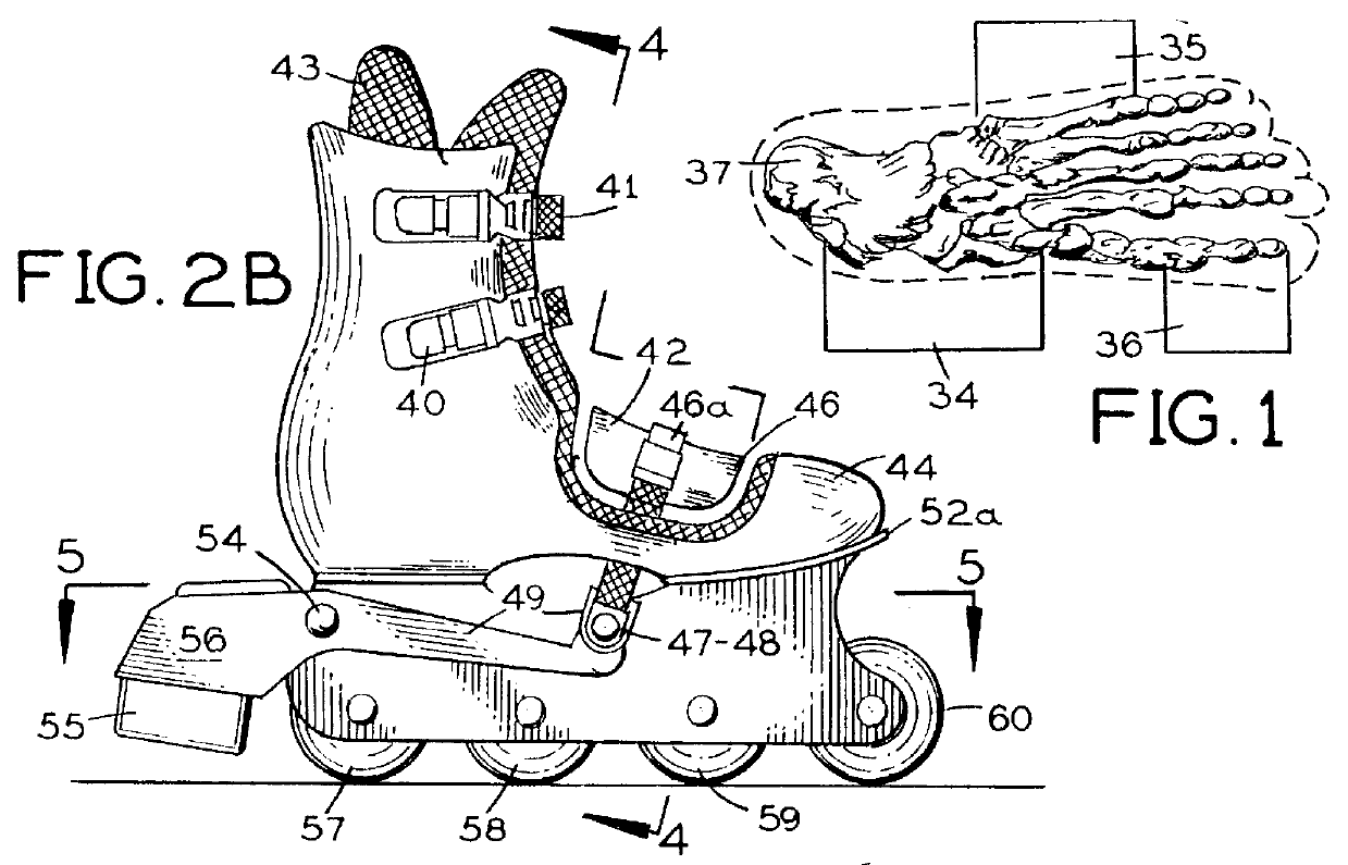
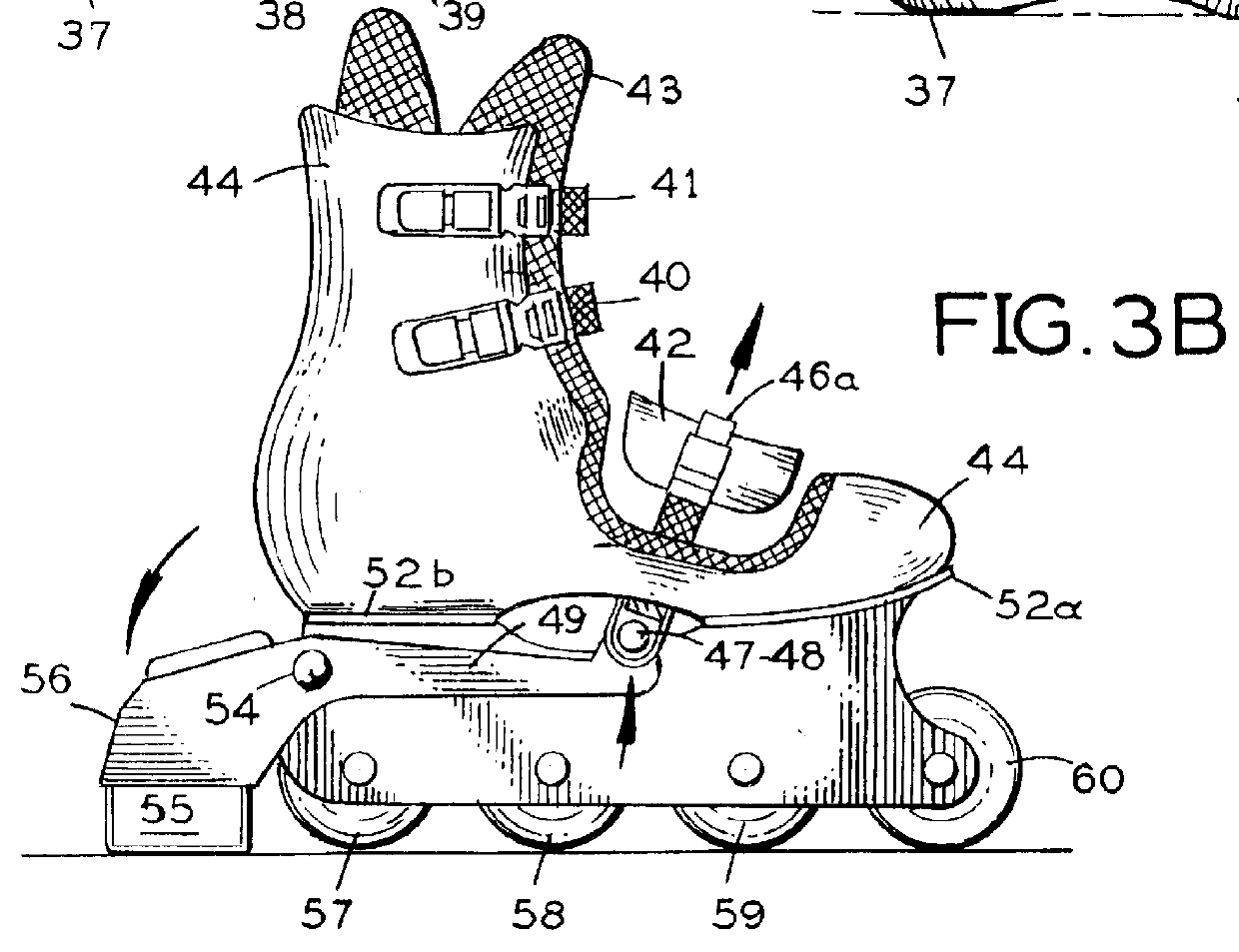
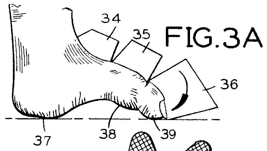
Ascribing to the drawings and primarily to FIGS. 1 through 3B, in accordance with the invention, a roller skates 20 chiefly includes a boot 44 rigidly mounted to a base from the base front portion 52a and rear portion 52b thereof and preferrably such that the hell and sole of the skater's feet when inside the boot will be parallel to the ground or rolled-on surface. The base includes two side-brackets 51a and 51b extending from the base front and rear portions where plurality of in-line wheels 57, 58, 59, 60 are mounted for rotation about a horizontal axis and rotating in the same vertical plane. The boot 44 maybe provided mainly of belt and buckle means 40 and 41 preferrably oriented above ankle to snugly and comfortably fastened the roller skates 20 to the skaters feet. A liner 43 maybe provided inside the boot to cushion the skater's feet inside the boot 44. Both the liner 43 and boot 44 are provided with sufficient opening preferrably above the tarsus 34 and metatarsus 35 of the...


PUM


Abstract

A roller skate provided with a brake mechanism operable when the foot or feet of the skater inside the boots are arctuated to an arch from the normal straight position inorder to effect braking. The braking system allows the skater to perform a single foot or two feet braking at will without changing the skater's postural position at the point of time when the brake was applied. It capitalize on the principle that when the foot or feet inside the boots are arctuated, they behave like structural arches to designed that when subjected to vertical loads, the feet end supports (namely the heels and phalanges ends) exerts reaction forces with inwardly directed components. It is stable and strong. The highest point or its crown, and the point which has the biggest movement, falls somewhere between the tarsus and metatarsus zones of its respective foot. Preferably, it is crown movement that is being used to drive a brake means inorder to create an effective and controllable braking. The present invention has utilized this principle in alliance with a brake means of the type that force amplifying to ensure a good margin of effective efficiency.

Description

1. Field of the InventionThe present invention relates to brake system of either the in-line type roller skates or the classic adjacent-wheel type, which allows the rider to effectively apply at will two-feet braking without any postural change at that time time the brake was applied by arcuating the skater's feet.It is paramount for roller skates to safely and effectively brake to stop as it is to roll smooth and swift. However, to date the publicly adapted brake system commercially popular are the ideas that were conceived in the late 40's and late 50's, such as the brake means mounted to front end of the roller skates or simply called as the Toe-Stop and for the in-line skate is the rear mounted brake means sometimes called as the Heel-Pad.There are quite a number of patents describing otherways of braking, but the fact of the matter is that the absolute judge in the field of success is the general public itself that celebrates the idea's undisfutable commercial adoption.2. Descr...

Claims


Application Information

Patent Timeline
IPC IPC(8): A63C17/14A63C17/00
CPCA63C17/1436A63C17/06A63C2017/1463
Inventor INTENGAN, FRANKLIN SANCHEZ
Owner INTENGAN FRANKLIN SANCHEZ
Why Eureka
Try Eureka