
Motor and guiding structure thereof

a guiding structure and motor technology, applied in the direction of lighting support devices, instruments, gearing, etc., can solve the problems of affecting the reliability of products, high manufacturing cost and time for forming the conventional guiding structure, and the width and thickness of the elastic sheet must be very thin, so as to reduce the vibration of the moving guiding unit, simplify the manufacturing process of the guiding structure, and improve product reliability and alignment accuracy.

Inactive Publication Date: 2011-01-11
DELTA ELECTRONICS INC
View PDF8 Cites 4 Cited by
  • Summary
  • Abstract
  • Description
  • Claims
  • Application Information

AI Technical Summary

Benefits of technology

This solution decreases vibration, enhances product reliability and alignment accuracy, and reduces manufacturing costs by simplifying processes and increasing the strength of the guiding structure.

Problems solved by technology

However, forming the elastic sheet and guiding groove on the side wall of the central opening of the base requires very precise processing technology, and thus the manufacturing cost and time for forming the conventional guiding structure are high.
In addition, since the elastic sheet is formed inside the small central opening of the base, the limitation of the size of the central opening and a certain distance must be provided between the elastic sheet and the side wall of the central opening, the width and thickness of the elastic sheet must be very thin.
Therefore, the elastic sheet may be broken or damaged during the movement of the guiding structure, thereby affecting the reliability of the product and causing the trouble of the user.
Moreover, the difficulties of manufacturing the mold and processing steps may also be increased, so that the manufacturing cost is increased, too.
Furthermore, the elastic sheet guides the guiding rod by deforming, so that the guiding rod may be unstable during its movement.

Method used


Image

  • Motor and guiding structure thereof
  • Motor and guiding structure thereof
  • Motor and guiding structure thereof

Examples


Embodiment Construction

[0019]The present invention will be apparent from the following detailed description, which proceeds with reference to the accompanying drawings, wherein the same references relate to the same elements.

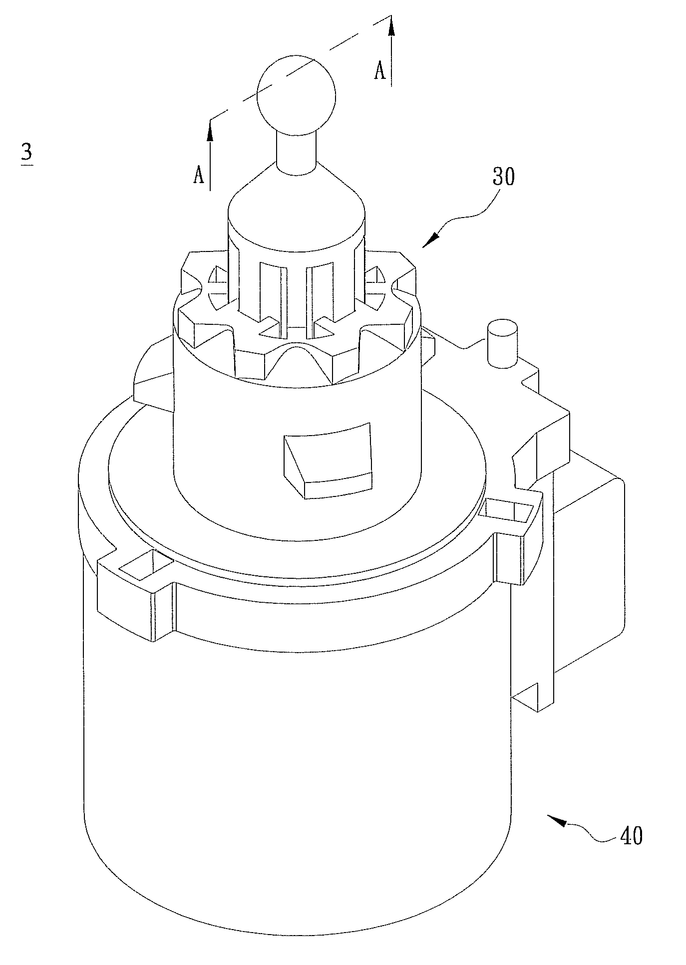
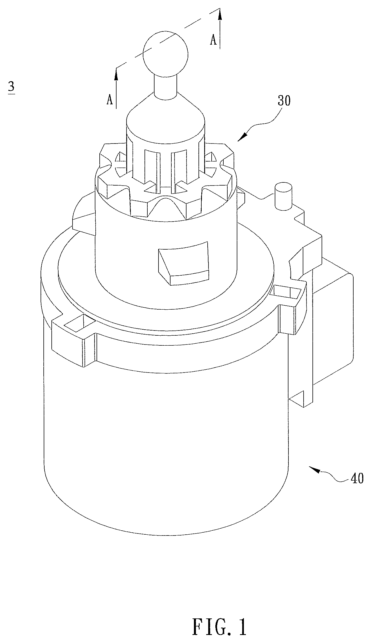
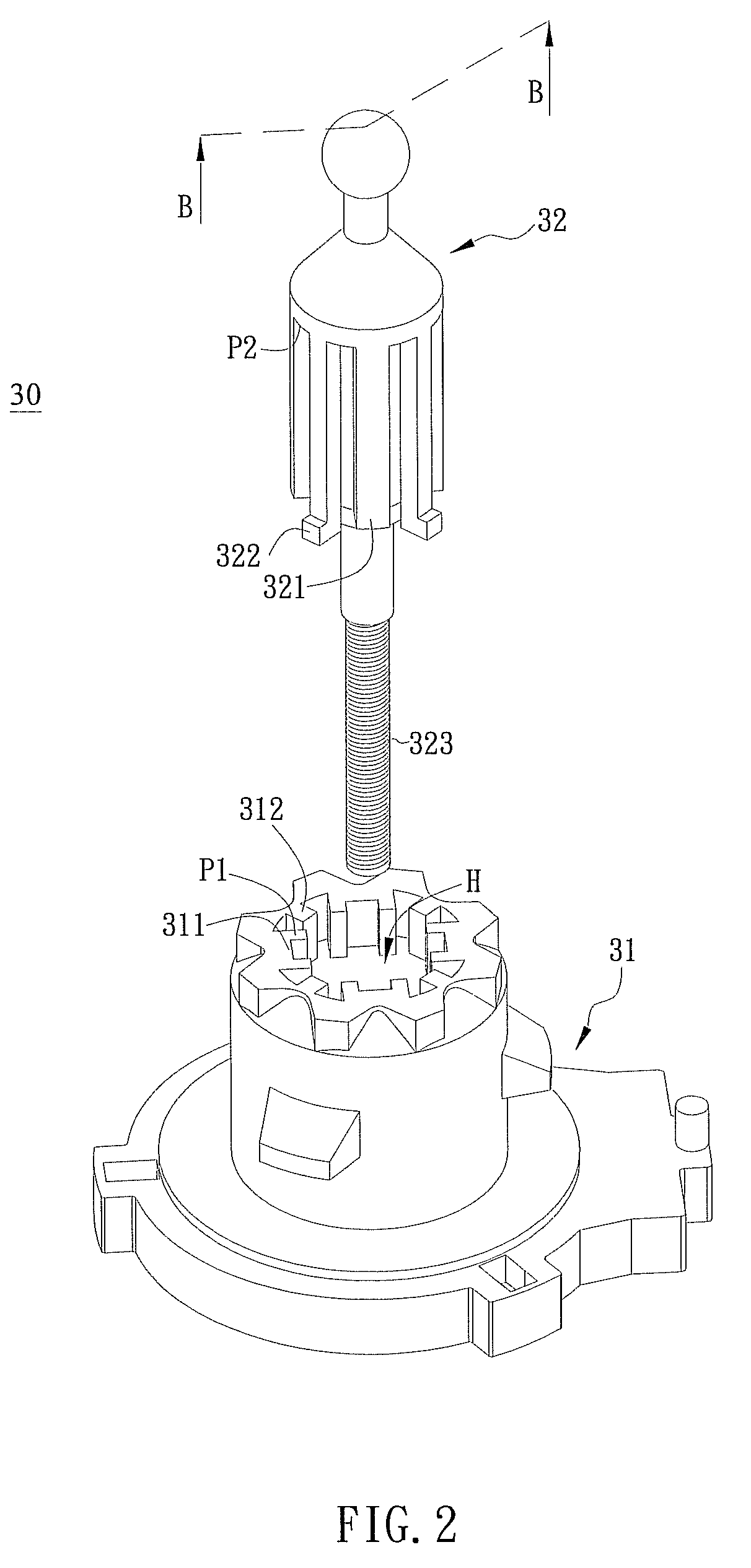
[0020]FIG. 1 is a schematic illustration showing a motor and a guiding structure according to an embodiment of the present invention. FIG. 2 is an exploded diagram of the guiding structure of the motor in FIG. 1. With reference to FIGS. 1 and 2, a motor 3 according to the embodiment of the present invention includes a motor body 40 and a guiding structure 30. In the embodiment, the motor 3 can be, for example but not limited to, a stepping motor for a headlight of a vehicle.

[0021]The guiding structure 30 is disposed on the motor body 40 and includes a base 31 and a guiding unit 32. The base 31 has an opening H, and the inner wall of the base 31, facing the opening H, is formed with at least one first guiding element 311 and at least one first restricting element 312, which is disposed...


PUM


Abstract

A guiding structure includes a base and a guiding unit. The base has an opening, and an inner wall of the base, facing the opening, is formed with at least one first guiding element and at least one first restricting element disposed adjacent to the first guiding element. The guiding unit is inserted into the opening and has at least one second guiding element and at least one second restricting element. The second guiding element is correspondingly coupled to or separated from the first restricting element by deforming, bending, rotating or displacing. The first guiding element is disposed corresponding to the second guiding element.

Description

CROSS REFERENCE TO RELATED APPLICATIONS[0001]This Non-provisional application claims priority under 35 U.S.C. §119(a) on Patent Application No(s). 096150221, filed in Taiwan, Republic of China on Dec. 26, 2007, the entire contents of which are hereby incorporated by reference.BACKGROUND OF THE INVENTION[0002]1. Field of Invention[0003]The present invention relates to a motor and a guiding structure thereof.[0004]2. Related Art[0005]The headlight for vehicles is usually cooperated with a motor and a guiding structure for adjusting the lighting angle of the headlight. In details, the guiding structure can convert the rotation of the motor into an axial force so as to provide the linear actions on the headlight, such as forward or backward. Thus, the headlight can be pushed to generate lights with different angles.[0006]The conventional guiding structure has a base and the guiding rod. The base has a plurality of elastic sheets, and the inner side of each elastic sheet has a guiding gr...

Claims


Application Information

Patent Timeline
Patent Type & Authority Patents(United States)
IPC IPC(8): B60Q1/04
CPCF16H25/2015H02K7/06F16H2025/204Y10T74/18056F16H2025/2078
Inventor HSU, CHIN-CHUYANG, CHUN-HUAHSU, CHIA-YING
Owner DELTA ELECTRONICS INC
Learn More