Multi-hydram Turbine System

Pending Publication Date: 2022-11-17
RENEWABLE OCEAN ENERGY INC
View PDF0 Cites 0 Cited by
  • Summary
  • Abstract
  • Description
  • Claims
  • Application Information

AI Technical Summary

Benefits of technology

The patent describes a system that uses a vertical siphon and a vector siphon to lift water from a water source to a turbine. This system can adjust the amount of water being delivered to the turbine, ultimately controlling the amount of electricity produced. The use of multiple siphon mechanisms allows for more water to be delivered to the turbine, increasing its rotational speed. The system is efficient and does not require a dam to create water flow, making it ideal for use in barrages or on ship or barges. The lower opening of the vertical siphon pipe is always below the surface of the water, ensuring continuous operation. The system is designed to be more eco-friendly and cost-effective than traditional hydroelectric systems.

Problems solved by technology

In a traditional hydram, pumping efficiency ranges from 60-80% but volumetric efficiency is limited by the ratio of the source head to a discharge head.
Increased water pressure results in an increase in the revolutions per minute (rpm) of the blades.

Method used


Image

  • Multi-hydram Turbine System
  • Multi-hydram Turbine System
  • Multi-hydram Turbine System

Examples


first embodiment

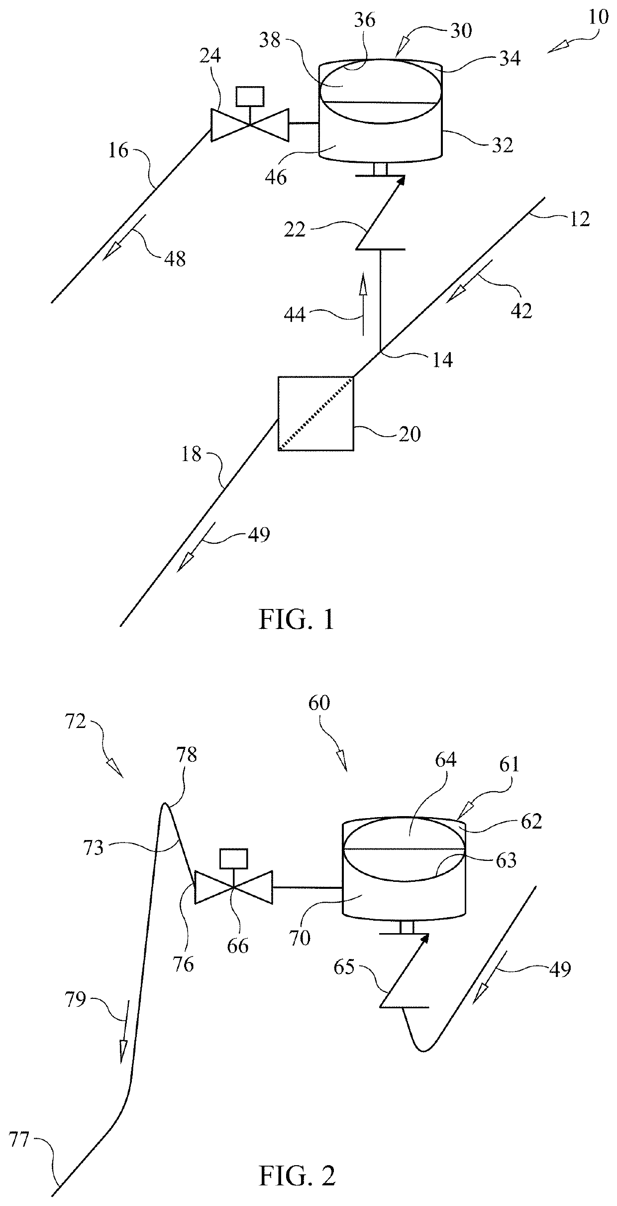
[0041]For a first embodiment, we refer to FIG. 1. Hydram system 10 comprises drive pipe 12, T-pipe 14, impulse valve 20, delivery valve 22, pressure vessel 30, release valve 24, delivery pipe 16, and waste pipe 18. Impulse valve 20 is a valve that closes sharply during flow such that it creates a sudden stoppage of the water in the valve and a reverse transmission of the kinetic energy causing a portion of the water to open delivery valve 22 and pass into pressure vessel 30. Delivery valve 22 is a check valve that is normally closed and only permits water into pressure vessel 30. Release valve 24 is a servo-controlled valve that opens at one pressure and closes at a second, lower, pressure. Pressure vessel 30 comprises sealed vessel 32 (preferably a steel vessel) enclosing fluid chamber 34 and flexible sealed chamber 36, with flexible sealed chamber 36 containing gas bolus 38. Gas bolus 38 in sealed chamber 36 acts to collect pressure energy and apply pressure to the fluid in fluid ...

second embodiment

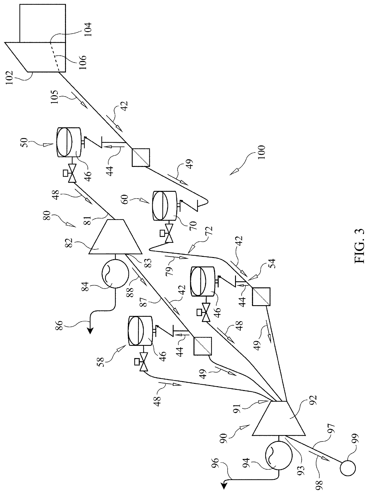
[0043]For a second embodiment, reflecting an active water multi-hydram system, we refer to FIGS. 1, 2 & 3. Active water system 100 comprises low head water source 102, primary hydram system 50, overflow pressure vessel system 60, primary hydroelectric turbine-generator system 80, secondary hydram system 54, tertiary hydram system 58, secondary hydroelectric turbine-generator system 90, and exhaust 99.

[0044]Primary hydram system 50, secondary hydram system 54, and tertiary hydram system 58 are each a structure according to hydram system 10 above, and function in the manner so described.

[0045]Overflow pressure vessel system 60 comprises sealed vessel 61, overflow inlet valve 65, overflow outlet valve 66, and siphon 72. Sealed vessel 61, preferably a steel or other rigid vessel, encloses fluid chamber 62 and flexible sealed chamber 63, with flexible sealed chamber 63 containing gas bolus 64. Gas bolus 64 in sealed chamber 64 acts to collect pressure energy and apply pressure to overflo...

third embodiment

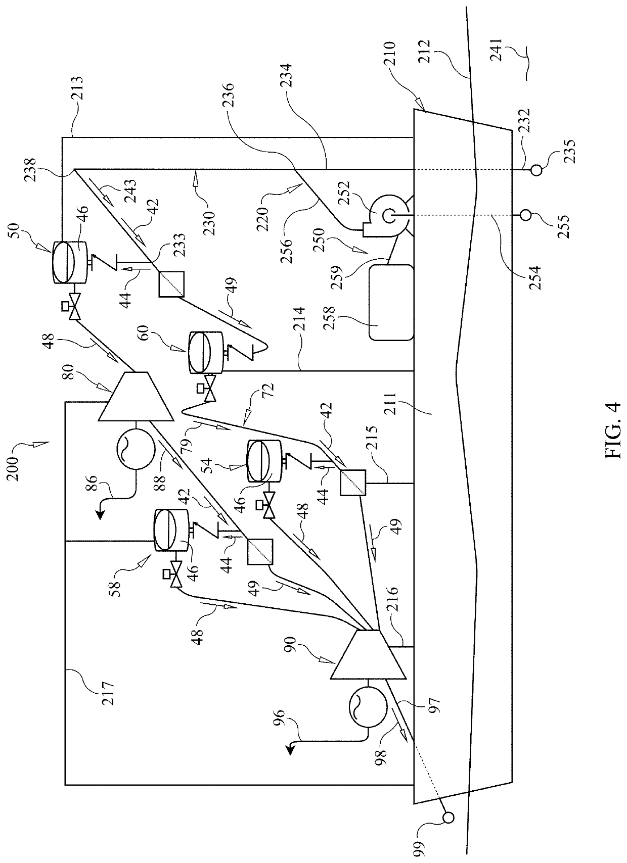
[0058]For a third embodiment, reflecting a passive water multi-hydram system, we refer to FIGS. 1, 2 & 4. Passive water system 200 comprises floating structure 210, siphon system 220, primary hydram system 50, overflow pressure vessel system 60, primary hydroelectric turbine-generator system 80, secondary hydram system 54, tertiary hydram system 58, secondary hydroelectric turbine-generator system 90, and exhaust 99.

[0059]Primary hydram system 50, secondary hydram system 54, and tertiary hydram system 58, overflow pressure vessel system 60, primary hydroelectric turbine-generator system 80, secondary hydroelectric turbine-generator system 90, and exhaust 99, are each a structure according to active water system 100 above and in FIG. 3, and function in the manner so described.

[0060]Floating structure 210 (which could be, e.g., a boat, barge, anchored platform) includes hull 211 floating on water 212, and supports siphon system 220, primary hydram system 50, overflow pressure vessel s...


PUM


Abstract

A hydropower system includes hydraulic ram system with a pressure vessel having a one-way inlet valve and an outlet valve controlling the release of pressurized water from the pressure vessel for use in a water turbine for providing electricity. A hydropower system may have two or more hydraulic ram systems with a first system feeding a first water turbine and a second and third system feeding a second water turbine. One or more siphons are provided to assist water flow, and an overflow pressure vessel captures and pressurizes waste water from the first hydraulic ram system for use in the third system, which releases pressurized water for the second water turbine. The second hydraulic ram system accepts spent water from the first water turbine and releases pressurized water for the second water turbine.

Description

REFERENCE TO RELATED APPLICATIONS[0001]This application claims priority to U.S. Provisional Patent Appl. No. 63 / 189,437 and incorporates that application in its entirety.FIELD OF THE INVENTION[0002]This disclosure relates generally to a hydroelectric turbine system and specifically to a hydroelectric turbine system comprising one or more hydraulic rams feeding a first turbine and one or more hydraulic rams feeding a second turbine, the system being adapted for use in both passive and active water environments.BACKGROUND OF THE INVENTION[0003]Hydroelectric power is the most cost-efficient form of renewable energy and is considered a mature industry as there have been few innovations in many years. Hydraulic rams (“hydrams”) have been used for hundreds of years to pump water without an external source of energy. The principles of hydraulic rams will be used to amplify the source head thereby improving the energy output of the turbine through increased rotational speed. Instead of the ...

Claims


Application Information

Patent Timeline
IPC IPC(8): F03B13/08F03B15/04
CPCF03B13/08F03B15/04Y02E10/20F05B2270/506
Inventor NAVARRO, RICHARD M.
Owner RENEWABLE OCEAN ENERGY INC
Why Eureka
Try Eureka