
Quench protection arrangement

Pending Publication Date: 2022-11-03
OXFORD INSTR NANOTECH TOOLS
View PDF0 Cites 0 Cited by
  • Summary
  • Abstract
  • Description
  • Claims
  • Application Information

AI Technical Summary

Benefits of technology

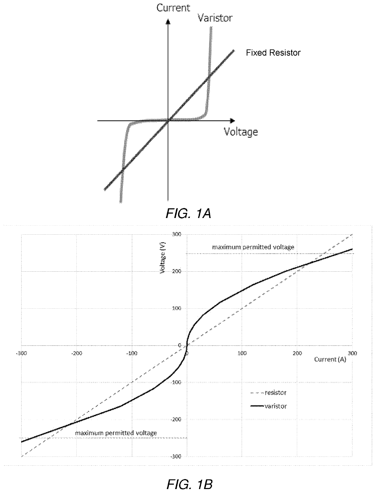
The patent text discusses the use of varistors in cryogenic environments to protect against magnet quench. These electronic components have a high resistance at lower voltages and a decreasing resistance with increasing current. By using varistors in protection circuits with low-temperature or high-temperature superconductor magnet sections, they can provide faster and more reliable quenching of a quench through the entire magnet. This can help mitigate the harmful effects of highly localised heating. The arrangement of multiple varistors and heaters connected in a protection circuit can enable quicker propagation of a quench across the entire magnet.

Problems solved by technology

Various conditions can cause a quench to occur, typically an excessive field, or rate of change thereof, inside the magnet, or a physical defect.
The resulting rapid, localised Joule heating at the part of the coil that has ceased to be superconductive, which is caused by the high current continuing to flow at that location, in turn raises the temperature of the surrounding regions.
When a quench occurs, the sudden decrease of current can result in inductive voltage spikes and arcing.
Magnets and other components can be damaged by these high-voltage and heating effects.
Additionally, with “wet” magnets that are maintained at their low operating temperatures by a cryogenic fluid, such as liquid helium bath magnets, the rapid conversion into heat of the large amount of energy that was stored in the magnet while it was operating as a superconductor causes a sudden, potentially explosive boil-off of the cryogenic fluid.
Moreover, with these “wet” magnets the aforementioned boil-off of fluid can create an asphyxiation hazard.
The current typically falls slowly, however, as the quench may take several seconds to propagate, depending on the size of the coil.
Existing solutions for quench protection suffer from a number of drawbacks.
For instance, when conventional resistors are used in protection arrangements with high field magnets, if an excess current passes through those resistors, they may melt and fail with an open circuit, with the possibility of electrical arcing to earth and between parts of the magnet in an uncontrolled manner.
In such scenarios damage may be caused to the magnet.
Moreover, voltages across magnet sections may take a long period to build (around 100 ms typically), which limits the responsiveness of protection provided by passive and passive with heater arrangements.

Method used


Image

  • Quench protection arrangement
  • Quench protection arrangement
  • Quench protection arrangement

Examples


Embodiment Construction

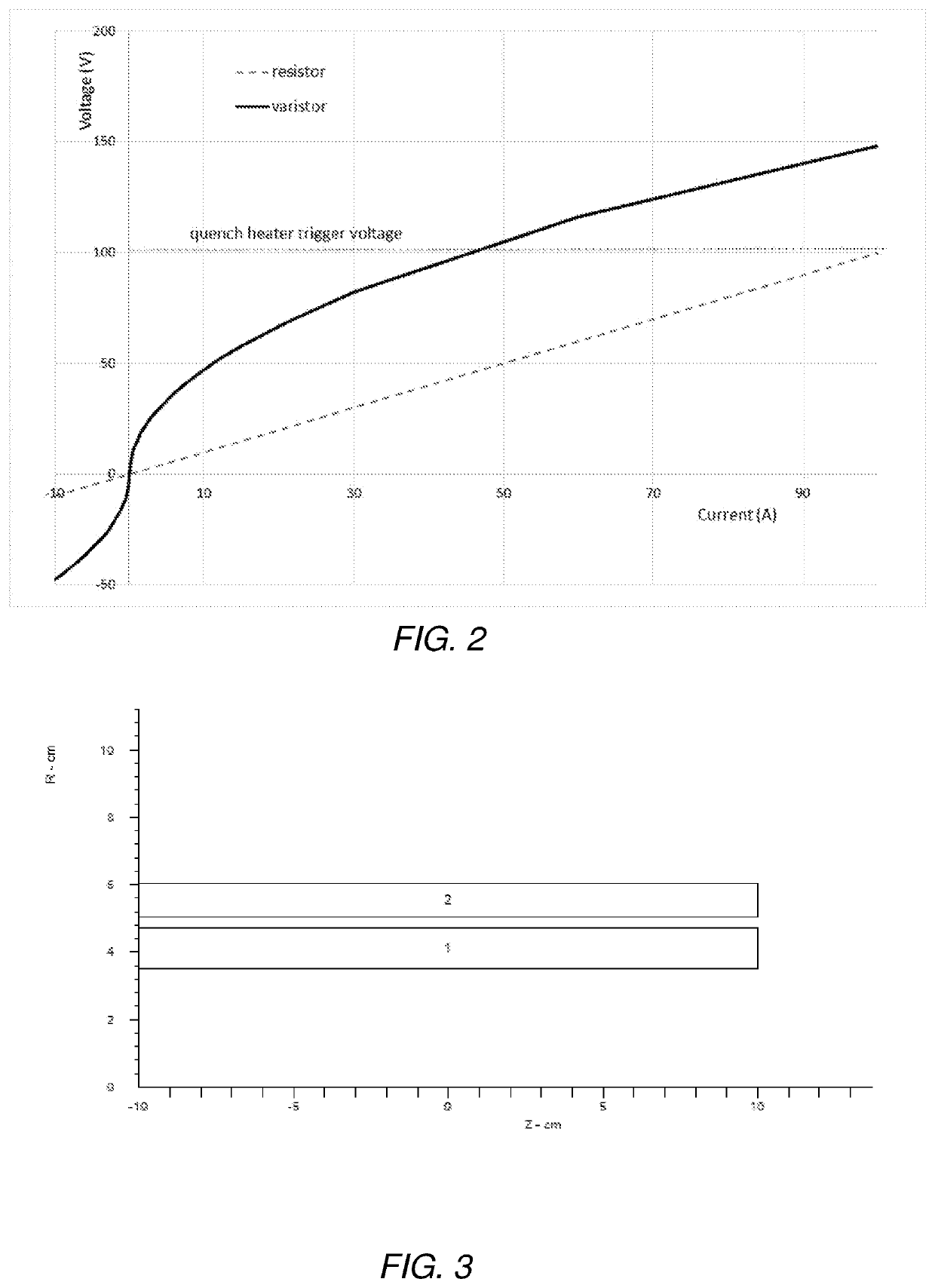
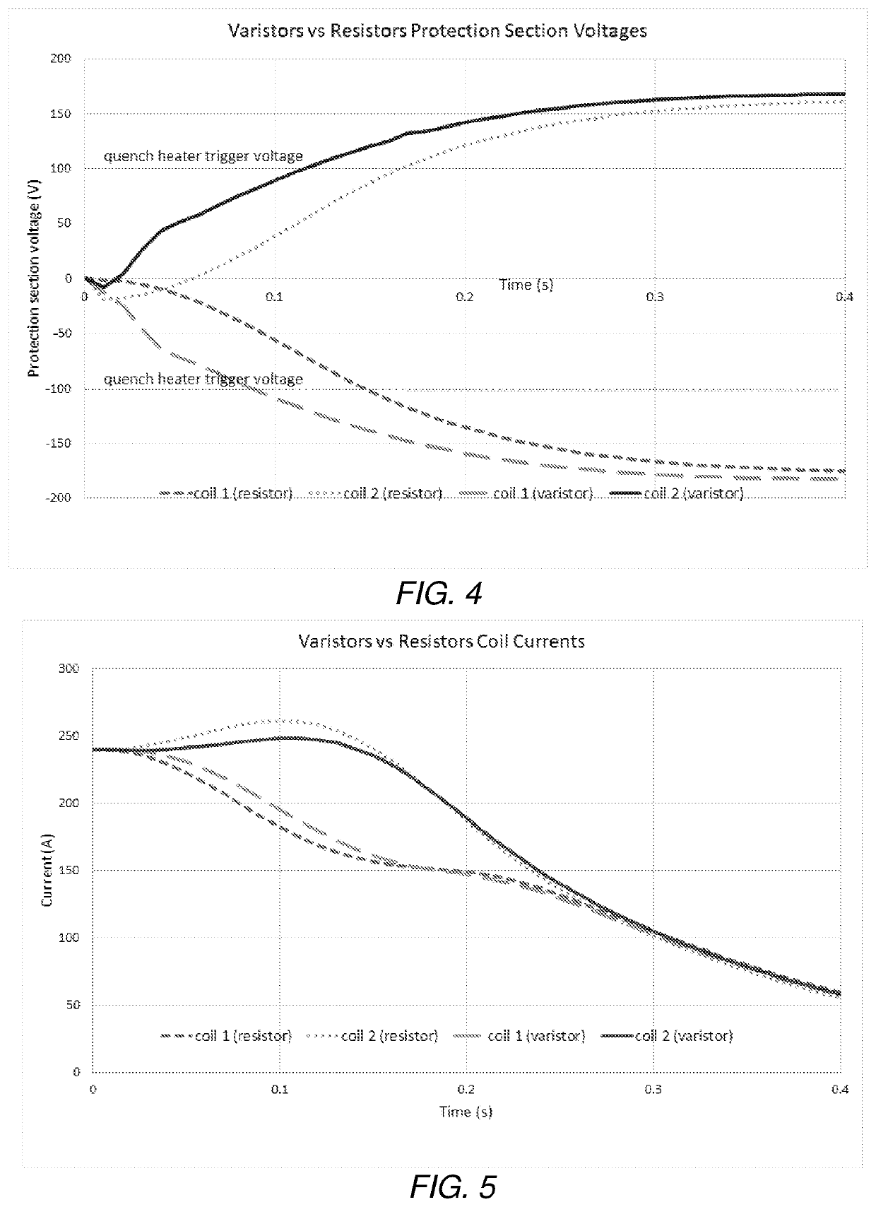
[0055]Quench modelling has been performed in order to demonstrate the capabilities of varistors in quench protection arrangements. For simplicity, and in view of the propensity for more complex modelled scenarios to render less clear the effect of the varistors or lead to systematic modelling errors, a simple, two-coil design has been used to test the concept. This is for illustrative purposes only, and it is envisaged that the quench protection arrangement may be implemented with any number of magnet coils. Computer software has been used to model the coil configuration and quench modelling.

[0056]FIG. 3 shows a cross-section through one half of the cylindrical coils as modelled in this general example. The coils are shown as cylindrical blocks centred on R=0 (corresponding to the y axis in the figure) and extending in the z direction (parallel with the x axis in the figure). Both coil 1 and coil 2 consist of NbTi wire of the same size and the coils have been chosen to have comparab...


PUM


Abstract

A quench protection arrangement for a superconducting magnet is disclosed. The arrangement comprises: a superconducting magnet comprising a plurality of magnet sections; a plurality of varistors, wherein each of the plurality of varistors is electrically connected in parallel across a respective one of the plurality of magnet sections; and a heater arrangement electrically connected to the plurality of varistors and configured to apply heat to each of the plurality of magnet sections in response to a change in a voltage across any one or more of the plurality of varistors. A method of protecting a superconducting magnet is also disclosed.

Description

FIELD OF THE INVENTION[0001]The present invention relates to a quench protection arrangement. In particular the invention relates to a quench protection arrangement for a superconducting magnet, the arrangement comprising a plurality of varistors connected across respective ones of a plurality of sections of a superconducting magnet.BACKGROUND TO THE INVENTION[0002]A quench in a superconductor, in particular a superconducting magnet, is a sudden loss of superconductivity therein and occurs when a part of a magnet coil reverts to a normal, resistive state. Various conditions can cause a quench to occur, typically an excessive field, or rate of change thereof, inside the magnet, or a physical defect. The resulting rapid, localised Joule heating at the part of the coil that has ceased to be superconductive, which is caused by the high current continuing to flow at that location, in turn raises the temperature of the surrounding regions. Consequently those regions are caused to enter a ...

Claims


Application Information

Patent Timeline
IPC IPC(8): H01F6/02H01C7/12H01C1/08G01R33/38
CPCH01F6/02H01C7/12H01C1/08G01R33/3804H01C13/02H02H7/001Y02E40/60
Inventor VARNEY, ANDREWTWIN, ANDYWARREN, DAVEVIZNICHENKO, ROMAN
Owner OXFORD INSTR NANOTECH TOOLS
Learn More