Biomimetic nanofiber tissue scaffolds

a biomimetic and nanofiber technology, applied in the field of biomimetic nanofiber tissue scaffolds, can solve the problems of limited regenerative ability, limited nanofiber materials, and unsustainable process

Active Publication Date: 2022-11-03
ULTRA SMALL FIBERS
View PDF1 Cites 0 Cited by
  • Summary
  • Abstract
  • Description
  • Claims
  • Application Information

AI Technical Summary

Benefits of technology

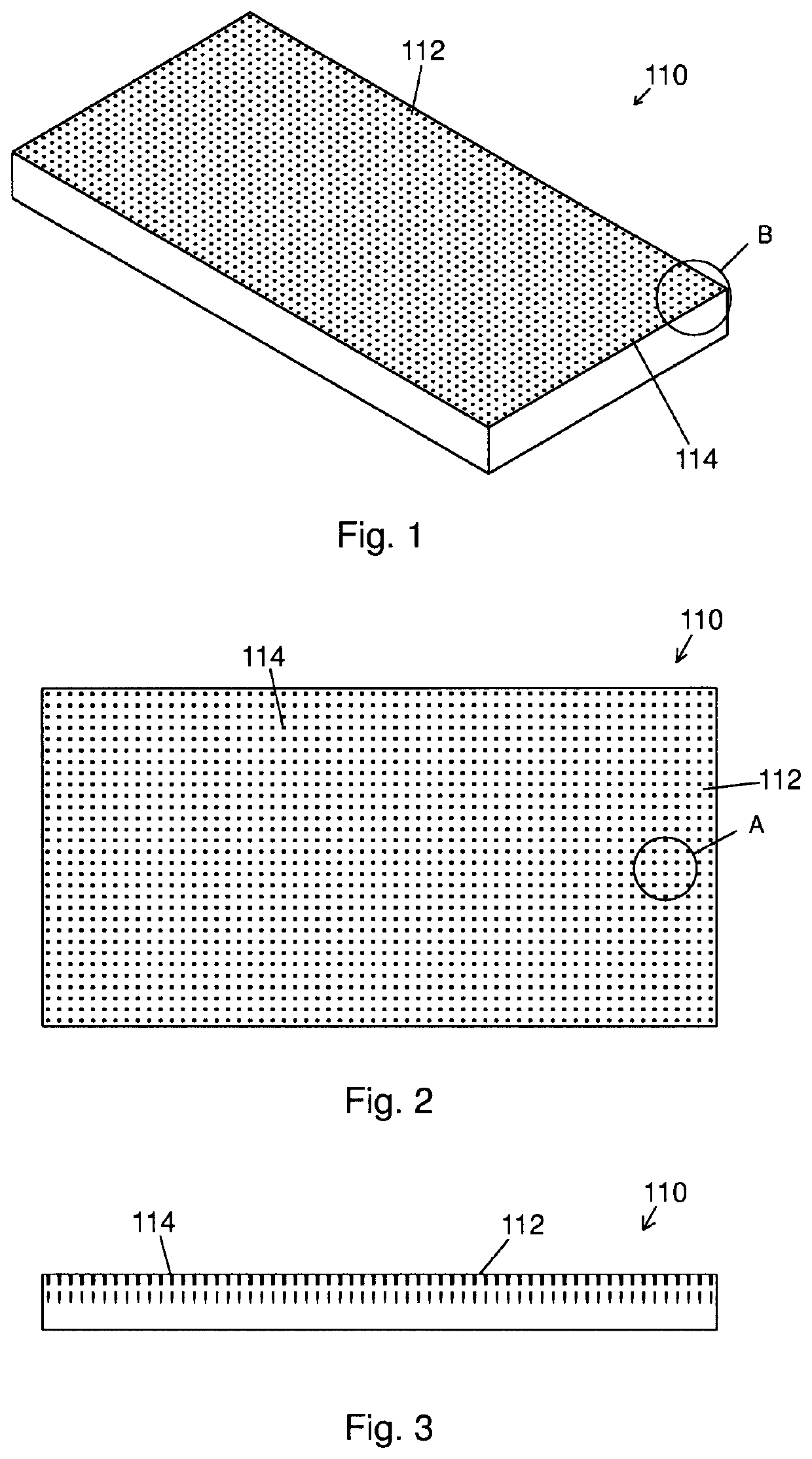
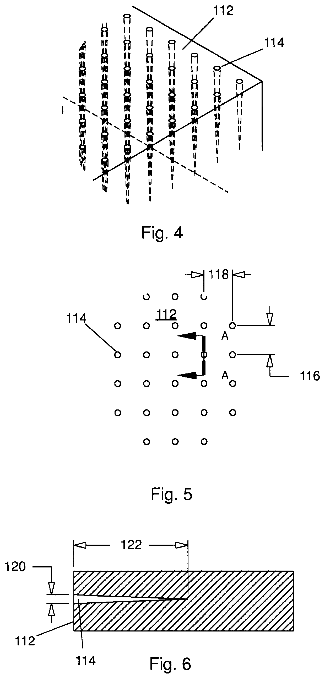
[0031]Scaffolds of the present invention mimic the tendril arrays present on the basement membrane of cross-linked collagen forming the ECM. This is accomplished by providing arrays of nanofibers formed on surfaces of the scaffold, the nanofibers of an array having a spacing similar to the collagen tendril attachment to a stiffer matrix of cross-linked fibers, and, like the tendrils, the nanofibers are substantially normal to the surface at the attachment site. The nanofibers may have somewhat irregular shapes in that they may have bumps, ridges, seams, and portions with asymmetric cross sections, however the nanofibers are generally tapered with a distally decreasing cross-section over their length. Each nanofiber may be viewed as a cantilevered beam with decreasing stiffness along its length, the greatest stiffness being adjacent to its attachment point to the surface. This allows secure attachment by cells through focal adhesions formed at the tips of the nanofibers, and also allows the creation of shear stresses between the scaffold and cells attached thereto. Additionally, nanofiber arrays of the present invention may provide outside-in signaling to cells within the scaffold that determine, for instance, the tendency of stem cells to maintain their “stemness” or to differentiate, and, in the case of differentiation, to increase the proclivity of the cells to differentiate to a preferred cell type.
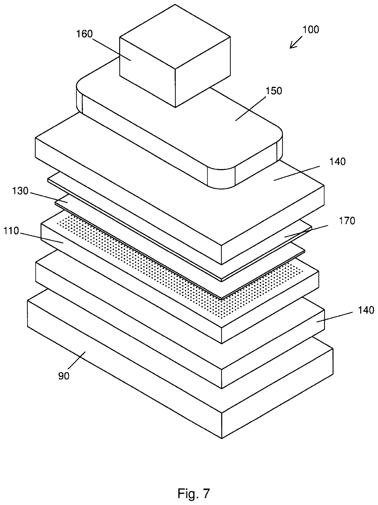
[0038]Scaffolds of the present invention may also be used for tissue augmentation. When a tendon or ligament is torn, the repair site is subject to re-injury during healing, and subsequent to healing due to the repaired region having insufficient strength. This may be avoided / minimized by augmenting the tissue at the repair site. This augmentation increases the strength of the repaired structure both during healing and after healing is complete. When implanting a tissue scaffold for tissue augmentation it is desirable that the scaffold have physical properties approximating those of the native tissue forming the structure into which the scaffold is implanted. Scaffolds of the present invention allow the strength, stiffness and resilience of the scaffold to be optimized through the physical dimensions of the bioribbons forming the scaffold without affecting the tuned topography of nanofiber arrays on the ribbon. Accordingly, scaffolds of the present invention may have optimal physical properties for an application and tuned nanofiber arrays that favorably affect tissue differentiation and propagation.

Problems solved by technology

While these treatments may be beneficial for some conditions, their regenerative abilities are limited because they lack a physiologically structured extracellular matrix (“ECM”).
It is not an environmentally friendly process due to the solvents required.
When forming nanofibers by electrospinning, the nanofiber materials are limited to polymers that can be mixed with a solvent to achieve the properties required for the process.
If there is retained solvent in the nanofibers, the behavior of cells within a scaffold formed therefrom may be adversely affected.
While the nanofibers of the previously described prior art examples are of a scale similar to fibrous tissue forming the ECM, they do not provide a biomimetic structure.
However, it must be noted that the fiber length in these “tuned” fibrous scaffolds is not controlled and therefore cannot be optimized for a given use.
Indeed, the average density and effective pore size can only be controlled within broad ranges.
Advantages that may be achieved through control of the length, orientation, and three-dimensional arrangement of fibers cannot be realized with current commonly used manufacturing techniques.
Naturally occurring structures within the body are not limited in the way that these manufactured scaffolds are limited.
Accordingly, while the manufactured scaffolds may be referred to as “biomimetic” in that they grossly mimic natural structures, their long continuous fibers, regardless of orientation, do not provide sites for cell attachment that mimic the tendrils of the ECM, and the focal attachments of the tendrils with their inherent ability to provide outside-in signaling to the cell, thereby affecting cell behavior.

Method used


Image

  • Biomimetic nanofiber tissue scaffolds
  • Biomimetic nanofiber tissue scaffolds
  • Biomimetic nanofiber tissue scaffolds

Examples


Embodiment Construction

[0131]While the making and using of various embodiments of the present invention are discussed in detail below, it should be appreciated that the present invention provides many applicable inventive concepts that are embodied in a wide variety of specific contexts. The specific embodiments discussed herein are merely illustrative of specific ways to make and use the invention and do not delimit the scope of the invention.

[0132]To facilitate the understanding of the embodiments described herein, a number of terms are defined below. The terms defined herein have meanings as commonly understood by a person of ordinary skill in the portions relevant to the present invention. Terms such as “a,”“an,” and “the” are not intended to refer to only a singular entity, but rather include the general class of which a specific example may be used for illustration. The terminology herein is used to describe specific embodiments of the invention, but their usage does not delimit the invention, excep...


PUM

PropertyMeasurementUnit
electrical potentialsaaaaaaaaaa
pore sizeaaaaaaaaaa
average lengthaaaaaaaaaa

Abstract

A biomimetic tissue scaffold for repairing an elongated tissue in need of repair can comprise a plurality of coiled flexible polymeric ribbons having a surface on which is formed an array of nanofibers, the ribbons forming a tubular body defining a first open end in which a first end of the elongated tissue is receivable, a second open end in which a second end of the elongated tissue is receivable, and a lumen extending between the first and second open ends.

Description

[0001]A portion of the disclosure of this patent document contains material that is subject to copyright protection. The copyright owner has no objection to the reproduction of the patent document or the patent disclosure, as it appears in the U.S. Patent and Trademark Office patent file or records, but otherwise reserves all copyright rights whatsoever.CROSS-REFERENCES TO RELATED APPLICATIONS[0002]Not Applicable.STATEMENT REGARDING FEDERALLY SPONSORED RESEARCH OR DEVELOPMENT[0003]Not Applicable.REFERENCE TO SEQUENCE LISTING OR COMPUTER PROGRAM LISTING APPENDIX[0004]Not Applicable.BACKGROUND OF THE INVENTION[0005]Stem Cells and the Extracellular Matrix[0006]The use of stem cells for regenerative treatment of injuries is now commonplace. Stem cells from bone marrow aspirate or other sources are frequently injected into knees as a treatment for arthritis. Embryonic stem cells derived from umbilical cord blood and tissue are introduced intravenously in an attempt to cure various chroni...

Claims


Application Information

Patent Timeline
Patent Type & Authority Applications(United States)
IPC IPC(8): A61L27/18A61L33/00A61L27/56C08J5/18
CPCA61L27/18A61L33/0082A61L27/56A61L33/0041C08J5/18A61L2430/36A61L2300/604A61L2300/42A61L2300/414A61L2430/02A61F2/0063A61F2/08A61F2/105A61F2210/0076A61F2002/0086A61B17/1128A61F2240/004A61F2230/0069A61F2230/0091A61F2230/0019A61B2017/00526B29L2031/7562
Inventor HOFMEISTER, WILLIAM H.VAN WYK, ROBERT A.ANDERSON, COLLIN D.
Owner ULTRA SMALL FIBERS
Why Eureka
Try Eureka