Drug delivery device with plunger rod having nonuniform stopper interface

a technology of plunger rod and plunger rod, which is applied in the field of medical devices, can solve the problems of overly fast transfer of rear chamber liquid to the front chamber, high cost, and discomfort of subcutaneous drug delivery, and achieves the effects of reducing the risk of infection, and reducing the safety of patients

Pending Publication Date: 2022-09-29
NOVO NORDISK AS
View PDF0 Cites 0 Cited by
  • Summary
  • Abstract
  • Description
  • Claims
  • Application Information

AI Technical Summary

Benefits of technology

The invention is for a drug delivery device that reduces the force required to set pistons or stoppers in motion. The device has a first force transferring portion that leads a second force transferring portion when the plunger rod structure moves distally along the reference axis to displace the elastomeric stopper. This results in a nonuniform pressure being exerted onto the rear stopper end, where initially a non-zero pressure is exerted onto the peripheral portion and zero pressure is exerted onto the remaining portion of the rear stopper end. The pressure on the peripheral portion causes a local breaking loose of rear stopper material from the interior wall such that when the second force transferring portion reaches the rear stopper end the bulk stopper displacement is easier because some of the stickiness has already been overcome. The invention provides a more homogenous force profile for a complete drug expelling action with the drug delivery device. The distal end face may be designed in various ways to achieve the desired effect. The invention also includes a stud that interacts with the rear stopper end to ensure proper alignment and minimize tilting of the elastomeric stopper during bulk advancement in the drug reservoir.

Problems solved by technology

Subcutaneous drug delivery is often associated with discomfort as many people dislike the thought of having an injection needle inserted through the skin.
A common drawback of such devices is the fact that during storage, over time, the piston material tends to adhere to the reservoir material, which means that a significant static friction must be overcome in order to initiate a drug mixing and / or expelling.
In case of a manually driven piston rod the sudden shift from static to kinetic friction as the pistons break loose is likely to cause a jerking forward motion of the pistons as the user tries to compensate for the sudden acceleration by significantly decreasing the force input.
Apart from being an unpleasant user experience it may in fact lead to an overly fast transfer of the rear chamber liquid to the front chamber.
If the front chamber carries a dry powder to be reconstituted the transfer process may even lead to undesired foaming.
A downside of this is that once the friction becomes kinetic the power available for the actual drug expelling is very high and may lead to an unpleasantly high speed of delivery.
Adding to that, a powerful spring requires stronger interfacing injection device parts to avoid creep or breakage during a potential medium- or long-term storage period in pre-loaded state, increasing both the cost and the weight of the injection device.
The described adherence of the piston material to the reservoir material may in fact be a challenge for single chamber reservoirs as well, even though only one piston needs to be mobilised and the required break loose force is relatively smaller.
Hence, the problems related to overcoming the static friction and controlling the speed of delivery are also pertinent to such devices as e.g. conventional syringes and automatic injection pens employing conventional drug cartridges.

Method used


Image

  • Drug delivery device with plunger rod having nonuniform stopper interface
  • Drug delivery device with plunger rod having nonuniform stopper interface

Examples


Embodiment Construction

[0042]When / If relative expressions, such as “upper” and “lower”, “left” and “right”, “horizontal” and “vertical”, “clockwise” and “counter-clockwise”, etc., are used in the following, these refer to the appended figures and not necessarily to an actual situation of use. The shown figures are schematic representations for which reason the configuration of the different structures as well as their relative dimensions are intended to serve illustrative purposes only.

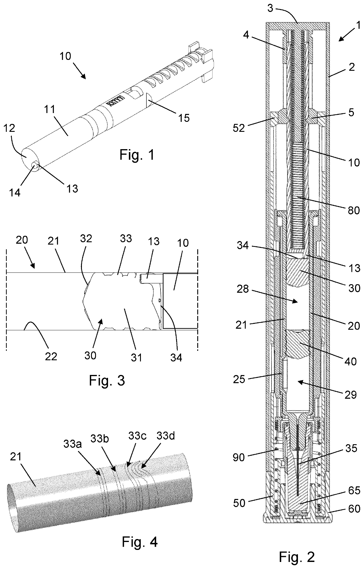
[0043]FIG. 1 is a perspective view of a plunger rod 10 for use in a drug delivery device according to an embodiment of the invention. The plunger rod 10 comprises a hollow elongated shaft 11 which extends along a longitudinal axis. At its front end the plunger rod 10 is provided with an abutment surface 12 adapted to abut a stopper in a drug reservoir during a drug administration action, as explained in more detail below. A peripheral stud 13 protrudes distally from the abutment surface 12 and has a leading end 14 for prepa...


PUM


Abstract

The present invention provides a drug delivery device (1) comprising: a drug reservoir (20) comprising a reservoir body (21) extending along a reference axis and an elastomeric stopper (30) arranged in the reservoir body (21), the elastomeric stopper (30) comprising a stopper body (31) extending between a front stopper end (32) and a rear stopper end (34) and having a plurality of axially spaced apart circumferential ribs (33) for sealing interaction with an interior wall (22) of the reservoir body (21), and a plunger rod structure (10) for displacing the elastomeric stopper (30) relative to the interior wall (22), the plunger rod structure (10) extending along the reference axis and comprising a distal end face (12, 14) adapted to interface with the rear stopper end (34). The distal end face (12, 14) comprises a first force transferring portion (14) and a second force transferring portion (12), the first force transferring portion (14) axially leading the second force transferring portion (12) and being adapted to interact with a peripheral portion of the rear stopper end (34).

Description

FIELD OF THE INVENTION[0001]The present invention relates to medical devices and more particularly to drug delivery devices with reservoirs having a volume which can be reduced by displacement of a piston or stopper.BACKGROUND OF THE INVENTION[0002]Within some medical treatment areas, a combination therapy involving co-administration of at least two drugs is advantageous because of synergistic or additive effects. For example, within diabetes care, in the management of type 2 diabetes mellitus, concomitant use of certain insulin and glp-1 products has been shown to reduce HbA1c levels in subjects, thereby improving glycaemic control.[0003]Many drugs must be administered parenterally to be effective in the body and some of these, e.g. insulin and glp-1, may require one or more doses to be delivered subcutaneously on a daily basis. Subcutaneous drug delivery is often associated with discomfort as many people dislike the thought of having an injection needle inserted through the skin. ...

Claims


Application Information

Patent Timeline
IPC IPC(8): A61M5/315A61M5/20A61M5/32
CPCA61M5/31596A61M5/2033A61M5/31515A61M5/3202A61M2005/202A61M2005/31598A61M5/31A61M5/3213A61M5/31513A61M2005/31521
Inventor BENDIX, KLAUSTRUE, DANIEL PATRICK GODSKESENSOERENSEN, DAN NOERTOFT
Owner NOVO NORDISK AS
Why Eureka
Try Eureka