
Vacuum cell configured for reduced inner chamber helium permeation

a vacuum cell and inner chamber technology, applied in the direction of positive displacement liquid engines, machines/engines, particle separator tubes, etc., can solve the problems of helium more rapidly permeating, unusable vacuum cells for uhv applications, and rendering the inner chamber unusable for its intended purpos

Pending Publication Date: 2022-08-18
COLDQUANTA
View PDF3 Cites 0 Cited by
  • Summary
  • Abstract
  • Description
  • Claims
  • Application Information

AI Technical Summary

Benefits of technology

The invention is about a vacuum cell with reduced inner chamber permeability, which means that the cell is designed to prevent the movement of atoms from the outer environment to the inner chamber where the vacuum is achieved. This is important for creating a high vacuum or ultra-high vacuum (UHV) in the inner chamber, which is important for various applications such as cold atom technologies and quantum computing. The invention addresses the issue of helium gas permeating the seal or bulk and rendering the inner chamber unusable for its intended purpose. The invention proposes various methods for reducing inner chamber permeability, including the use of a moat, evacuating the inner chamber, and selecting materials with low permeability to helium. The invention aims to provide a vacuum cell with reduced inner chamber permeability to improve its effectiveness and lifespan.

Problems solved by technology

Eventually, the helium gas can raise the pressure in the inner cell above a desired vacuum range, rendering the inner chamber unusable for its intended purpose.
Thus, helium may more rapidly permeate to the inner chamber through the depletion or transition region and render the vacuum cell unusable for UHV applications.
Although techniques for mitigating helium permeation are available, there are drawbacks.
Consequently, such techniques only prolong effective device lifetime.

Method used


Image

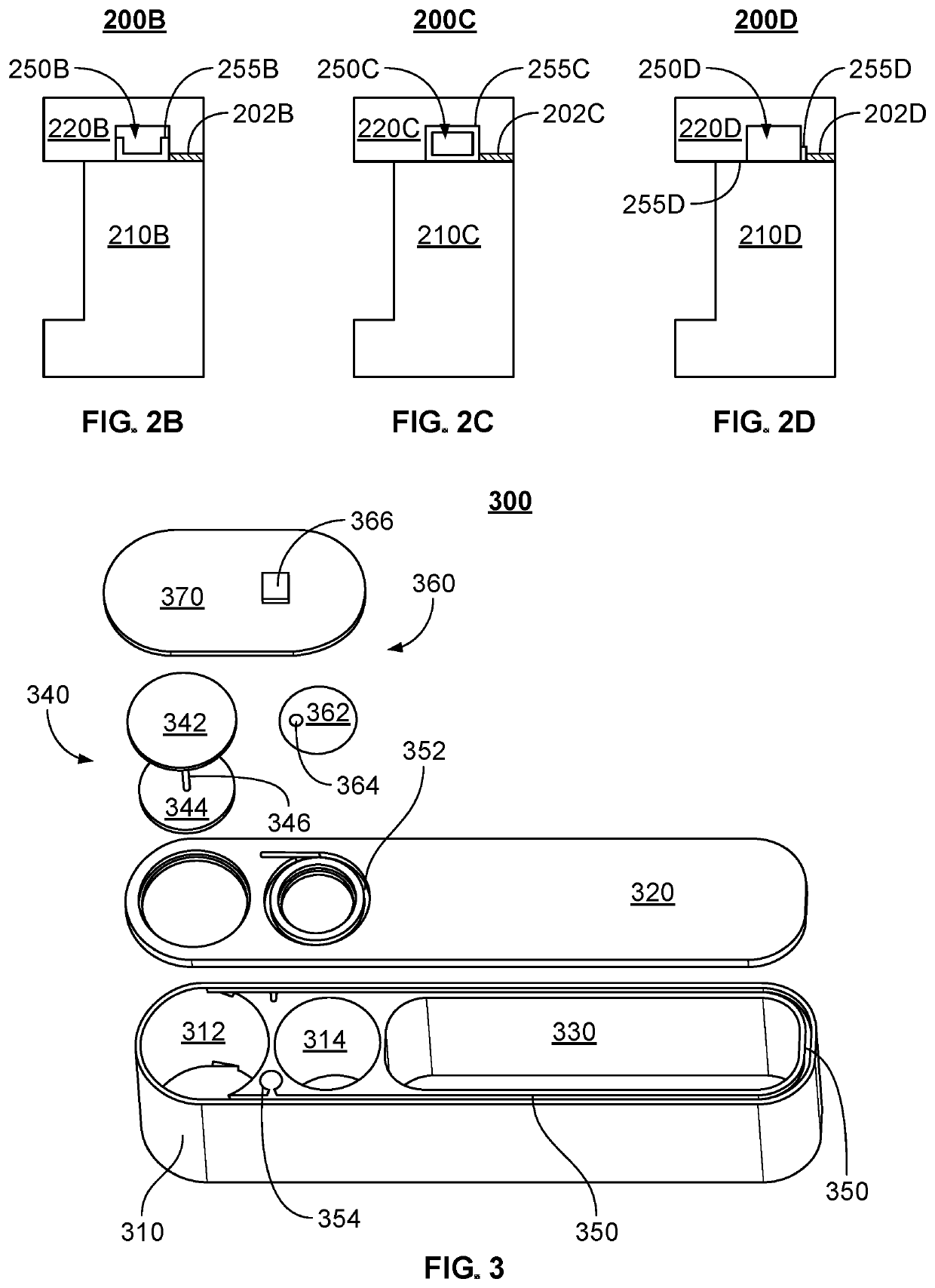
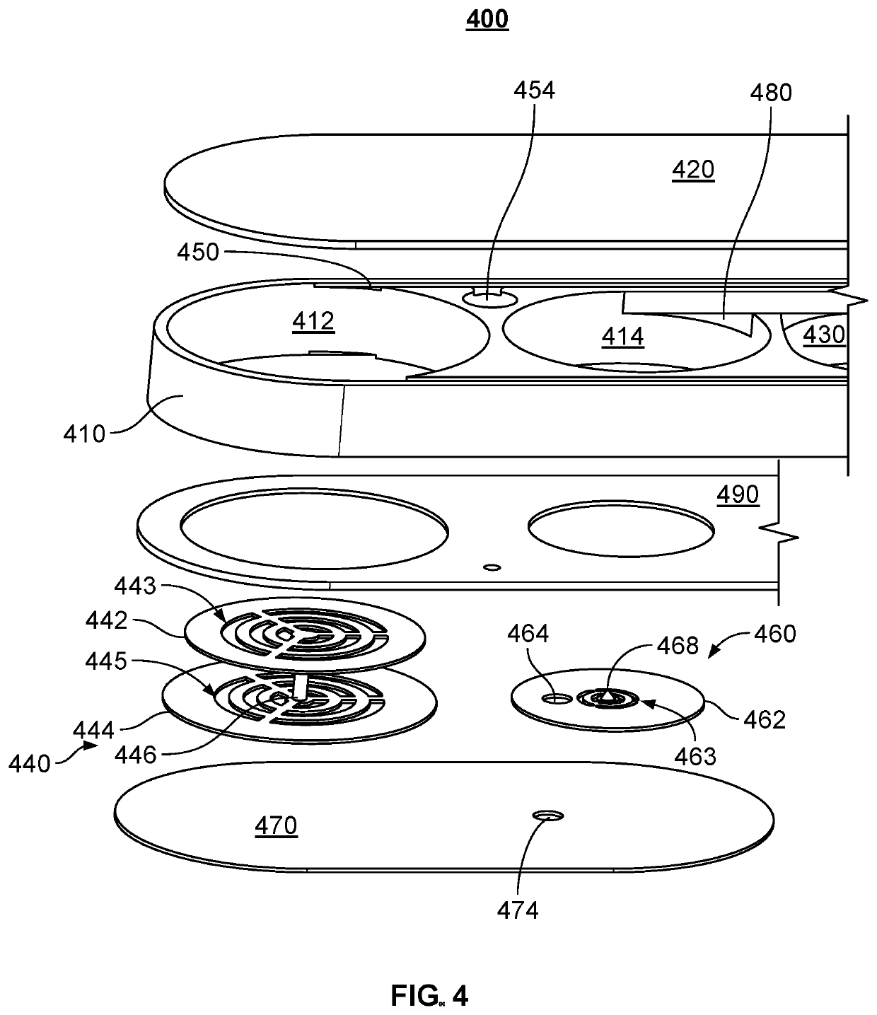
  • Vacuum cell configured for reduced inner chamber helium permeation
  • Vacuum cell configured for reduced inner chamber helium permeation
  • Vacuum cell configured for reduced inner chamber helium permeation

Examples


Embodiment Construction

[0015]The invention can be implemented in numerous ways, including as a process; an apparatus; a system; and / or a composition of matter. In this specification, these implementations, or any other form that the invention may take, may be referred to as techniques. In general, the order of the steps of disclosed processes may be altered within the scope of the invention. Unless stated otherwise, a component described as being configured to perform a task may be implemented as a general component that is temporarily configured to perform the task at a given time or a specific component that is manufactured to perform the task.

[0016]A detailed description of one or more embodiments of the invention is provided below along with accompanying figures that illustrate the principles of the invention. The invention is described in connection with such embodiments, but the invention is not limited to any embodiment. The scope of the invention is limited only by the claims and the invention enc...


PUM


Abstract

A vacuum cell is described. The vacuum cell includes an inner chamber, a buffer channel, and a buffer ion pump. The buffer channel is fluidically isolated from the inner chamber and fluidically isolated from an ambient external to the vacuum cell. The buffer ion pump is fluidically coupled to the buffer channel and fluidically isolated from the ambient and the inner chamber.

Description

CROSS REFERENCE TO OTHER APPLICATIONS[0001]This application claims priority to U.S. Provisional Patent Application No. 63 / 149,249 entitled VACUUM CELL WITH BUFFER ION PUMP filed Feb. 13, 2021 which is incorporated herein by reference for all purposes.BACKGROUND OF THE INVENTION[0002]Vacuum cells capable of achieving a high vacuum or an ultra-high vacuum (UHV), e.g. pressures of 10−9 Torr or less, in inner chambers may be utilized in a number of applications. For example, such vacuum cells may be used in cold atom technologies, in which atoms in the inner chamber reach and are maintained at temperatures well under 1 K. Cold atoms in such vacuum cells may be used in quantum computing, basic research, sensors, as well as other technologies.[0003]In some cases, such vacuum cells may have their inner chambers evacuated and hermetically sealed. Hermetic sealing generally prevents the movement of atoms from the ambient (i.e. outside of the vacuum cell) to the inner chamber in which the UHV...

Claims


Application Information

Patent Timeline
IPC IPC(8): H01J41/12
CPCH01J41/12F04B37/04F04B37/14F04B2015/082
Inventor HUGHES, STEVEN MICHAEL
Owner COLDQUANTA
Learn More