
Thermoelectric module and refrigerator comprising same

a technology of thermoelectric modules and refrigerators, which is applied in the direction of domestic cooling devices, lighting and heating devices, and machine operation modes, etc., can solve the problems of reducing the temperature of the heat absorption surface, affecting the heat absorption effect, and destroying cells, etc., to improve the heat transfer effect, reduce the thickness of the thermoelectric module, and improve the soldering stability of the semiconductor element

Pending Publication Date: 2022-07-28
LG ELECTRONICS INC
View PDF0 Cites 0 Cited by
  • Summary
  • Abstract
  • Description
  • Claims
  • Application Information

AI Technical Summary

Benefits of technology

The patent describes a new design for a thermoelectric module used in refrigerators and other cooling systems. The design has several benefits. First, by eliminating a ceramic substrate and reducing the thickness of the module, it can be more compact. Second, changing the material of the plating layer of the semiconductor element from tin to gold improves solder wetting, making the semiconductor element more stable. Third, the removal of the ceramic substrate eliminates the need for a separate coating process, simplifying the manufacturing process and reducing costs. Fourth, instead of using a thick ceramic substrate, a heat dissipation sheet can be interposed in both ends of the semiconductor device, improving heat transfer. Fifth, the need for sealing the side surface of the thermoelectric element is eliminated, simplifying the manufacturing process and reducing costs.

Problems solved by technology

However, when food such as meat or seafood is stored in the frozen state in the existing freezing compartment, moisture in cells of the meat or seafood are escaped out of the cells in the process of freezing the food at the temperature of −20° C., and thus, the cells are destroyed, and taste of the food is changed during an unfreezing process.
However, in the case of the refrigerator using the thermoelectric module disclosed in the prior art, since a heat generation surface of the thermoelectric module is configured to be cooled by heat-exchanged with indoor air, there is a limitation in lowering a temperature of the heat absorption surface.
Then, there is a problem that heat absorbed from the heat absorption surface is not transferred to the heat generation surface quickly.
In the case of the thermoelectric module disclosed in the prior art, since the heat generation surface is cooled by the indoor air, there is a limit that the temperature of the heat generation surface is not lower than a room temperature.
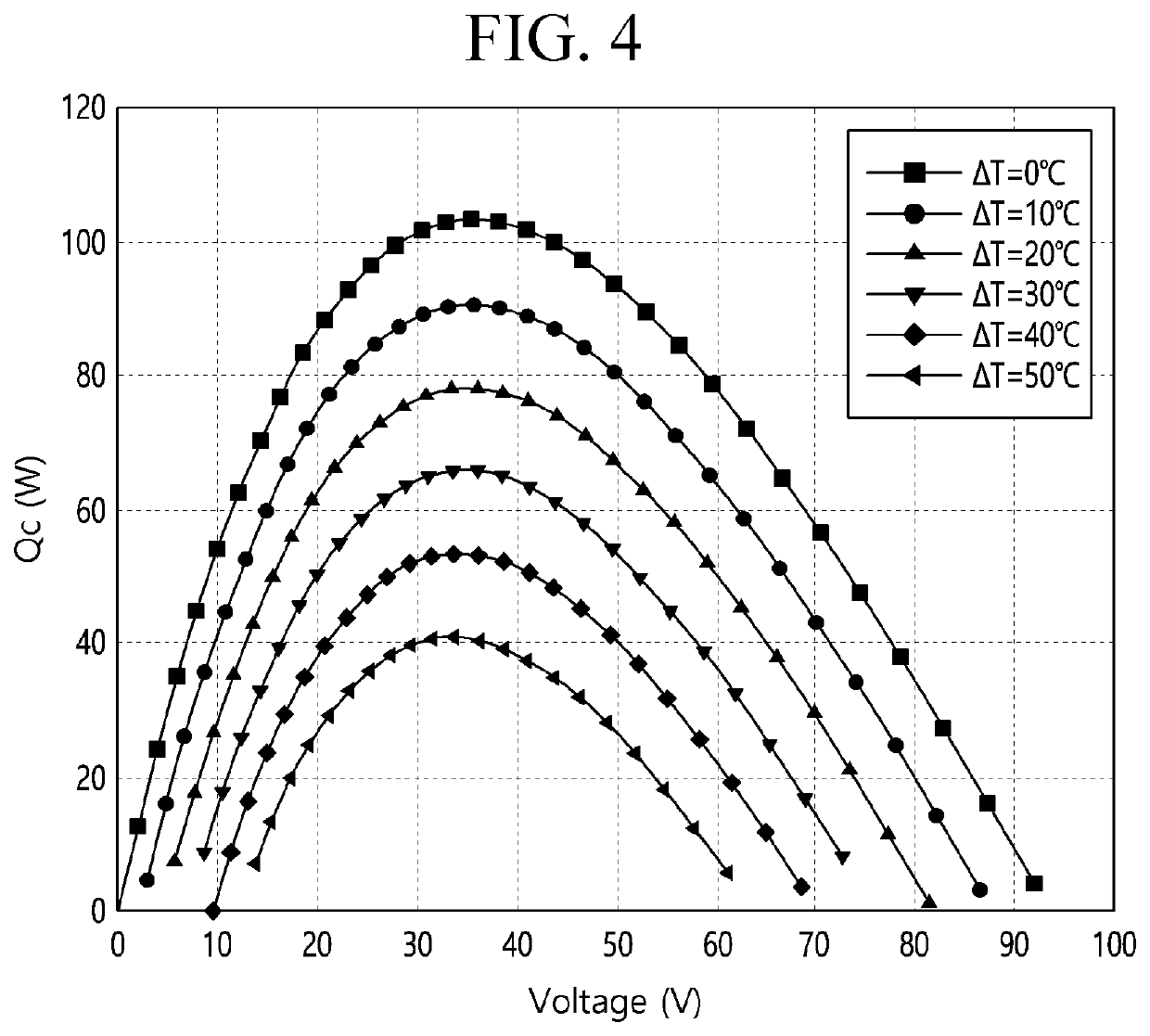
In a state in which the temperature of the heat generation surface is substantially fixed, the supply current has to increase to lower the temperature of the heat absorption surface, and then efficiency of the thermoelectric module is deteriorated.
In addition, if the supply current increases, a temperature difference between the heat absorption surface and the heat generation surface increases, resulting in a decrease in the cooling capacity of the thermoelectric module.

Method used


Image

  • Thermoelectric module and refrigerator comprising same
  • Thermoelectric module and refrigerator comprising same
  • Thermoelectric module and refrigerator comprising same

Examples


first embodiment

[0172]FIG. 8 illustrates a cross-sectional view of a thermoelectric module according to a first embodiment.

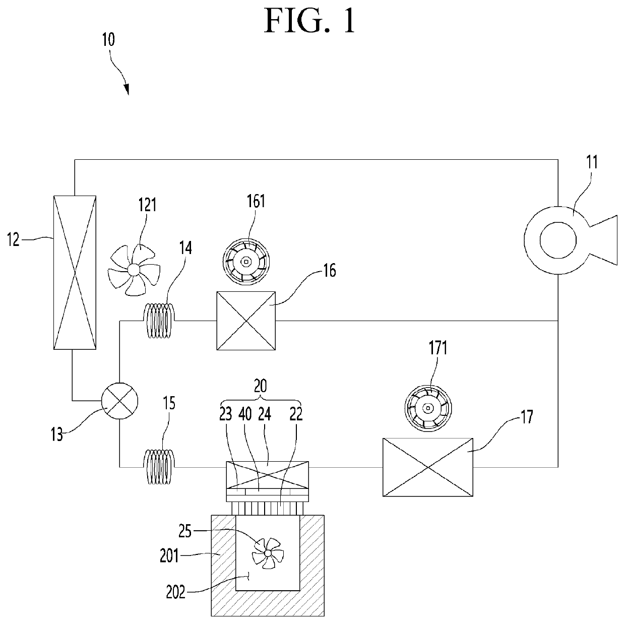
[0173]Referring to FIG. 8, a thermoelectric module 20 according to a first embodiment of the present invention includes a thermoelectric element 40, a cold sink 22 attached to a heat absorption surface of the thermoelectric element 40, a heat sink 24 attached to a heat generation surface of the thermoelectric element 40, and a sealing cover 26 connecting edges of the cold sink 22 and the heat sink 24 to each other.

[0174]As described above, the heat sink 24 may be an evaporator through which a low-temperature refrigerant flows, but it should be noted that, like the cold sink 22, a metal member having high thermal conductivity may be used.

[0175]In detail, the thermoelectric element 40 may include a semiconductor element portion including a P-type semiconductor element 41 and an N-type semiconductor element 42, a heat absorption-side electrode 43 provided at one end of the semicon...

second embodiment

[0190]FIG. 9 is a cross-sectional view of a thermoelectric module according to a second embodiment of the present invention.

[0191]Referring to FIG. 9, in a thermoelectric module 20a according to a second embodiment of the present invention, two thermoelectric elements 40a and 40b are disposed between a cold sink 22 and a heat sink 24, and the two thermoelectric elements 40a and 40b has a structure partitioned by a heat transfer block 27.

[0192]Also, in the thermoelectric module 20a according to the present embodiment, like the thermoelectric module 20 according to the first embodiment, a sealing cover 26 is surrounded around an edge of the cold sink 22 and an edge of the heat sink 24 to prevent foreign substances from being introduced into the thermoelectric module 20a.

[0193]Also, like the thermoelectric module 20 according to the first embodiment, a heat dissipation sheet portion replaces a ceramic substrate.

[0194]In detail, the two thermoelectric elements constituting the thermoel...

third embodiment

[0261]FIG. 10 is a cross-sectional view of a thermoelectric module according to a third embodiment of the present invention.

[0262]Referring to FIG. 10, in a thermoelectric module 20b according to a third embodiment of the present invention, as in the second embodiment, the ideas in which two thermoelectric modules 51 and 52 is disposed between a cold sink 22 and a heat sink 24 is the same. However, there is a slight difference in configuration of the two thermoelectric modules 51 and 52.

[0263]In detail, the thermoelectric module 20b according to the third embodiment may include a cold sink 22, a first thermoelectric element 51 having a heat absorption surface attached to the cold sink 22, a second thermoelectric element having a heat absorption surface that is thermally conductively connected to a heat generation surface of the first thermoelectric element 51, a heat sink 24 attached to a heat generation surface of the second thermoelectric element 52, and an intermediate substrate ...


PUM


Abstract

A thermoelectric module according to an embodiment of the present invention may comprise: a cold sink; a thermoelectric element having a heat absorption surface coupled to the cold sink; a heat sink coupled to a heating surface of the thermoelectric element to dissipate heat transferred from the cold sink to the outside of the thermoelectric element; and a sealing cover for connecting the edge of the cold sink and the edge of the heat sink to surround the thermoelectric element, wherein the cold sink, the heat sink, and the thermoelectric element may be integrally formed by the sealing cover.In addition, the thermoelectric element may be a cascade type thermoelectric element in which two thermoelectric elements having the same or different specifications are coupled to each other.

Description

TECHNICAL FIELD[0001]The present invention relates to a thermoelectric module and a refrigerator including the same.BACKGROUND ART[0002]In general, a refrigerator is a home appliance for storing food at a low temperature, and includes a refrigerating compartment for storing food in a refrigerated state in a range of 3° C. and a freezing compartment for storing food in a frozen state in a range of −20° C.[0003]However, when food such as meat or seafood is stored in the frozen state in the existing freezing compartment, moisture in cells of the meat or seafood are escaped out of the cells in the process of freezing the food at the temperature of −20° C., and thus, the cells are destroyed, and taste of the food is changed during an unfreezing process.[0004]However, if a temperature condition of the storage compartment is set to a cryogenic state that is significantly lower than the current temperature of the freezing temperature. Thus, when the food quickly passes through a freezing po...

Claims


Application Information

Patent Timeline
Patent Type & Authority Applications(United States)
IPC IPC(8): H01L35/32H01L35/22H01L35/30
CPCH01L35/32H01L35/30H01L35/22F25B21/02F25D2317/061F25D11/025F25D11/022F25B2600/2511F25B25/00F25B5/02F25B5/04F25B41/20F25B2600/2507H10N19/101H10N10/17H10N10/13F25D23/12F25D15/00F25B2321/023F25B2321/0251F25B2321/0212H10N10/81H10N10/855
Inventor YUN, SEOKJUNLIM, HYOUNGKEUNLEE, JUNGHUNLEE, HOYOUN
Owner LG ELECTRONICS INC
Learn More