
Stirrer

a technology of stirrer and stirrer body, which is applied in the direction of liquid degasification, separation process, transportation and packaging, etc., can solve the problems of affecting the increase of temperature, cavitation, and cavitation, and achieve the effect of facilitating processing such as refinement, homogenization or emulsification, and suppressing the generation of cavitation

Pending Publication Date: 2022-07-28
M TECHN
View PDF0 Cites 0 Cited by
  • Summary
  • Abstract
  • Description
  • Claims
  • Application Information

AI Technical Summary

Benefits of technology

The present invention provides a stirring device that can effectively stir fluids without causing cavitation. This allows for improved processing such as refinement, homogenization, or emulsification. The device achieves this by increasing the speed of the fluid at the penetrating part of the stator, where it flows through an open and close mechanism. This reduces the generation of cavitation and allows for efficient shearing, resulting in fine dispersion or emulsification. The device also helps achieve particles with a narrow particle diameter distribution and uniform particle diameter.

Problems solved by technology

However, according to Examples described in Patent Documents 3 and 4, the rotation speed of rotor is very fast, it is naturally in the rotation speed of 25 m / s or more, and the rotor is operated at the rotation speed of 35 m / s or more, so that problem of cavitation occurs.
In addition, when the fluid is discharged by the rotor and passes through the opening of the stator, increase and decrease of the pressure is repeated thereby affecting the increase of the temperature in a microscopic region, thus the cavitation occurs.
Even if the processing such as atomization can be successfully performed by cavitation with an experimental machine, the situation often occurs that the processing using the cavitation cannot be reliably reproduced at the time of scaling up.
Nowadays, it may include the concept of evaporation, but as the real problem, the erosion due to cavitation is a serious problem.
This is because when erosion occurs, not only vibration of the machine, but it also leads to damage to the machine.
However, when the width of the slit is made too wide, the pressure of the fluid to be processed passing though the slit decreases which leads to slow the discharge flow speed thereof, thus the processing ability decreases.
On the other hand, when the width of the slit is made narrow, the discharge speed becomes faster, however in the case that the width is made too narrow, the pressure loss increases which leads to decrease the flow amount of the fluid to be processed passing through the slit, so that the discharge flow may not be generated well, or the hollowing phenomenon may occur.
As a result, there has been a limitation to increase the number of the slit by narrowing the slit width.
Regrettably, a precise analysis of cavitation is difficult with current flow analysis simulation technology.
In Patent Documents 4 and 5, it is considered that the speed of the intermittent jet stream passing through the stator is close to the sound speed in the water including air bubbles, and when the speed of the jet stream exceeds the sound speed, a shock wave is generated and damage to the machine occurs.
However, since Patent Document 6 does not fully consider to suppression of the cavitation, the problem of cavitation cannot be eliminated due to the remarkable increase in the power and widening of the pressure distribution in the processing part.

Method used


Image

  • Stirrer
  • Stirrer
  • Stirrer

Examples


Embodiment Construction

[0059]Hereinafter, with referring to the drawings, embodiments of the present invention will be explained.

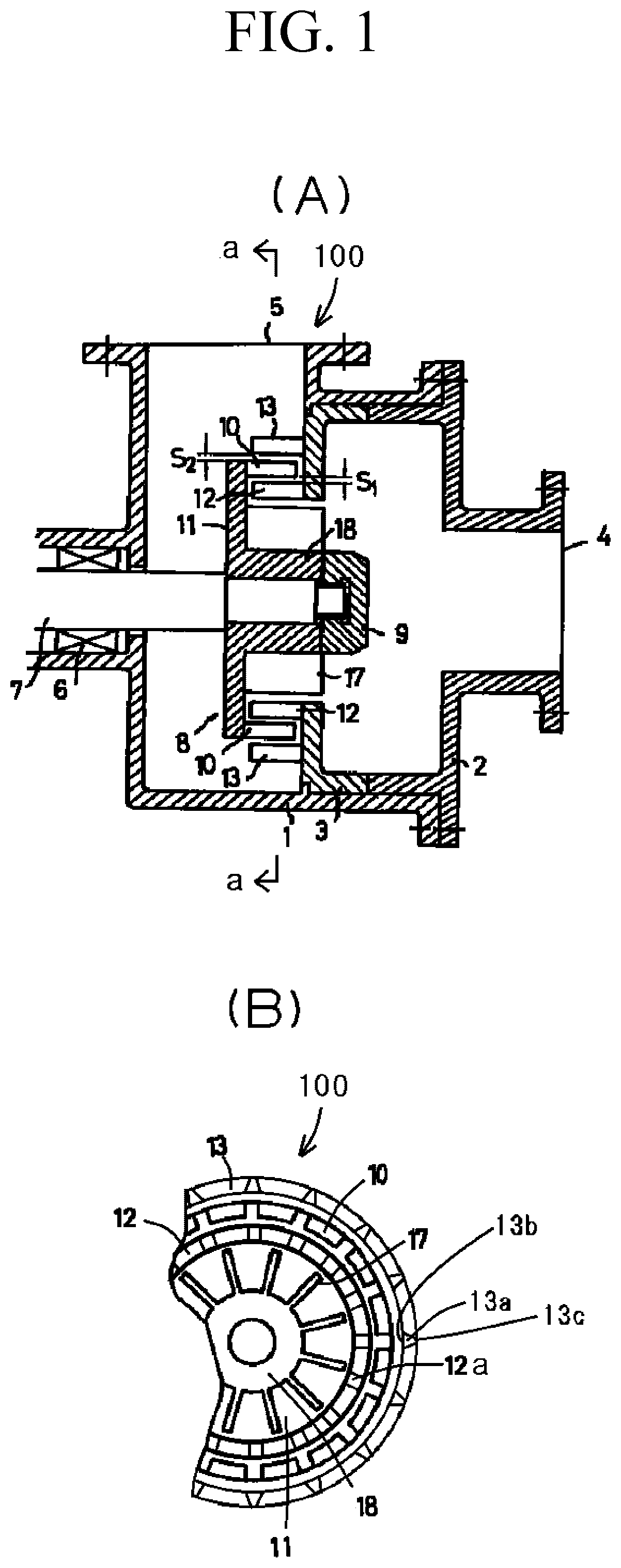
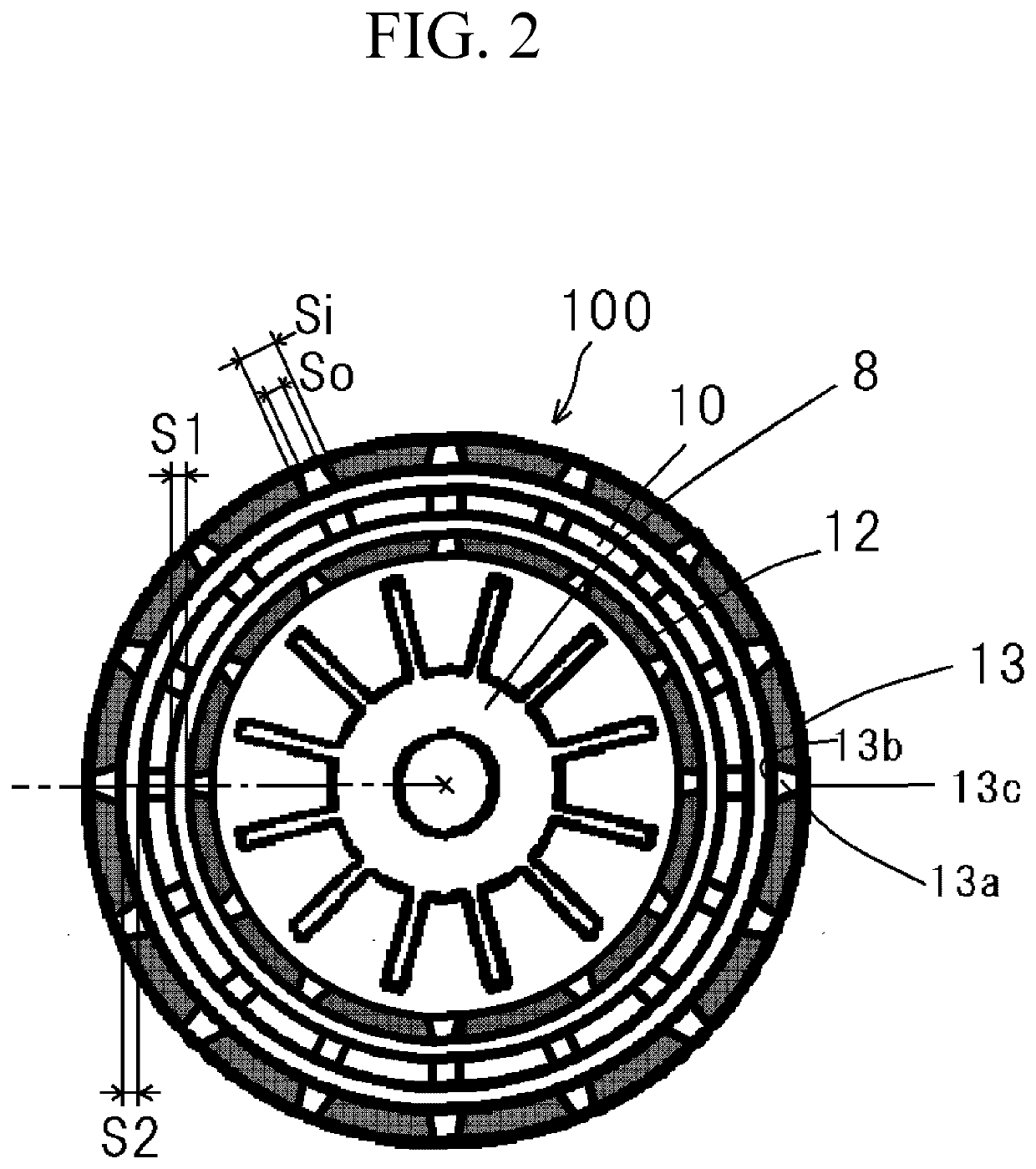
[0060]An example of a stirrer 100 suitable for carrying out the present invention is shown in FIG. 1(A), and an example of applying the present invention to the stirrer 100 of FIG. 1(A) is shown in FIG. 1(B) and FIG. 2.

[0061]In FIG. 1, reference number 1 denotes a casing, and a stator 3 is fixed by a suction cover 2. A suction port 4 is provided on the suction cover 2, and a discharge port 5 is provided on the casing 1. A main shaft 7 is rotatably provided so as to penetrate a shaft seal device 6 provided in the casing 1. A rotor 8 is fixed to the front end of the main shaft 7 by means of a nut 9.

[0062]A plurality of rotor cutters 10 intermittently provided on the rotor 8 along a circumferential direction are provided while being supported by a shroud 11. In the stator 3, stator cutters 12 and 13 are intermittently arranged along a circumferential direction in such a way as to c...


PUM

PropertyMeasurementUnit
Lengthaaaaaaaaaa
Lengthaaaaaaaaaa
Areaaaaaaaaaaa

Abstract

In an agitator in which cavitation arising during treatment of a fluid being treated is suppressed, a stator part S is provided with a plurality of penetration parts in the circumferential direction of the stator part S, and a stator main part positioned between adjacent penetration parts. When a fluid is discharged from the inside of the stator part S to the outside through the penetration part by the rotation of a rotor, in the stator part S for the agitator treating the fluid, the side facing a blade of the rotor is an inner wall surface, the side facing a blade of the rotor is an inner wall surface, the side facing the side opposite to the blade of the rotor is an outer wall surface, an opening of the plurality of penetration parts that is provided in the inner wall surface is an inflow opening, and an opening of the plurality of penetration parts that is provided in the outer wall surface is an outflow opening, the opening area of the inflow opening being larger than the opening are of the outflow opening.

Description

TECHNICAL FIELD[0001]The present invention relates to improvement of a stirrer, especially a stirrer used for refinement, homogenization, emulsification, or dispersion of a fluid to be processed.BACKGROUND ART[0002]Various stirrers have been proposed as an apparatus to carry out processing of emulsification, dispersion, or mixing of a fluid, however, today, it is required that the stirrer can satisfactorily process a fluid to be processed containing a substance having a small particle diameter such as nanoparticle.[0003]For example, a bead mill and a homogenizer are known as a kind of widely known stirrer, emulsifier, and disperser.[0004]There is a problem in the bead mill, however, that a crystal state in surface of particle is destructed and damaged thereby decreasing in a performance thereof. In addition, there is a big problem of generation of foreign materials as well as a high-cost problem of the beads which are frequently replaced or fed.[0005]In a high-pressure homogenizer, ...

Claims


Application Information

Patent Timeline
IPC IPC(8): B01F27/271B01F25/60
CPCB01F27/2711B01F2215/0431B01F23/41B01F27/1921B01D17/0217B01D19/0052B01F25/4511B01F25/105B01F25/60B01F27/70B01F27/72B01F27/1125B01F27/114
Inventor ENOMURA, MASAKAZU
Owner M TECHN
Learn More