Machining unit and method for machining a component

Pending Publication Date: 2022-07-14
AB SKF
View PDF0 Cites 0 Cited by
  • Summary
  • Abstract
  • Description
  • Claims
  • Application Information

AI Technical Summary

Benefits of technology

The patent describes a machining system that can remove excess material from a component's surface using an abrasive tool. The system controls the movement of the tool in a way that ensures it is always normal to the surface, which prevents the tool from removing more or less material depending on its contact angle. Additionally, the system includes a tool interface that automatically changes the used abrasive tool, which increases the production rate of the machining unit.

Problems solved by technology

Depending on the size of the component, this procedure may be rather time consuming.
Also, an orientation of the honing stone with regard to the surface of the component may vary such that the material removal capacity of the honing stone is not used to full capacity which may also lead to longer machining times.
Furthermore, even slight misalignments of the honing stone may lead to a lower or a higher removal rate which results in an uneven surface of the component.
Usually, the movement path of the honing stone has to be manually adjusted and is less flexible regarding adaptions for different movement paths, which may also lead to longer total machining times.

Method used


Image

  • Machining unit and method for machining a component
  • Machining unit and method for machining a component

Examples


Embodiment Construction

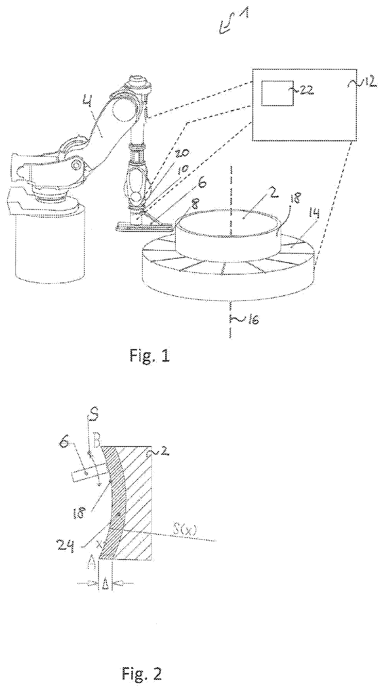
[0030]FIG. 1 shows a schematic view of a machining unit 1 for machining a bearing component 2, such as a bearing ring as shown in FIG. 1. The component may be a bearing component, for example a bearing ring having a diameter larger than 400 mm as shown in FIG. 1. The machining unit 1 includes an industrial robot 4, which is equipped with an abrasive tool 6 having an abrasive belt 8. However, the abrasive tool 6 may not be limited to an abrasive belt 8 and may alternatively be an abrasive stone. An abrasive belt 8 is a belt made form a carrier material on which an abrasive material, such as aluminum oxide (Al2O3), silicon carbide (SiC) or cubic boron nitride (CBN) is provided. During operation, the abrasive belt 8 rotates. The abrasive tool 6 is coupled to the industrial robot 4 via a tool interface 10.

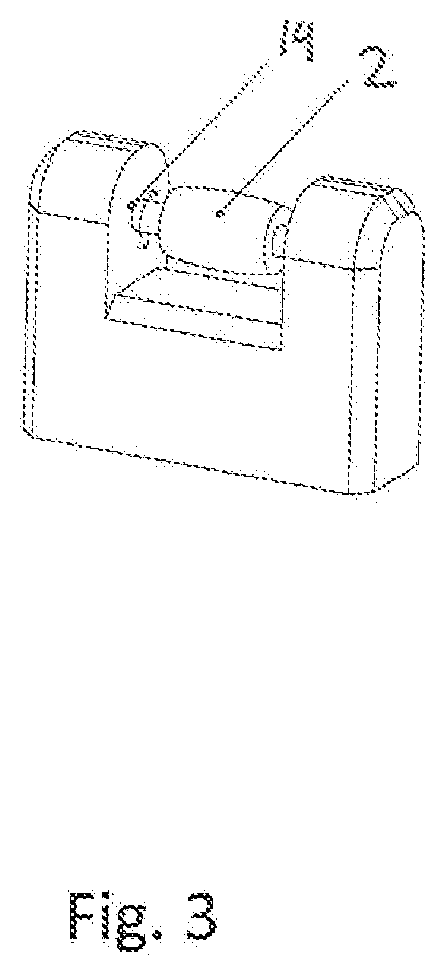
[0031]The component 2 is held by a holder 14. The holder 14 rotates around a rotation axis 16, which also causes the component 2 to rotate. To remove material from a surface 18 of the ...


PUM

PropertyMeasurementUnit
Lengthaaaaaaaaaa
Lengthaaaaaaaaaa
Lengthaaaaaaaaaa

Abstract

Disclosed is a machining unit for machining a bearing component. The machining unit includes an industrial robot and at least one abrasive tool. The at least one abrasive tool is coupled to the industrial robot and a controller. The controller is configured to control a movement path of the at least one abrasive tool such that a contact of the abrasive tool is in the normal direction to a surface of the component.

Description

CROSS-REFERENCE TO RELATED APPLICATIONS[0001]This application claims priority to German Patent Application no. 102021100314.8, filed Jan. 11, 2021, the contents of which is fully incorporated herein by reference.FIELD OF THE INVENTION[0002]The present invention relates to a machining unit for machining a component, particularly a bearing component. The present invention relates further to a method for machining a component, particularly a bearing component.BACKGROUND OF THE INVENTION[0003]One step in finishing a bearing component is the machining with an abrasive tool to provide a smooth component surface. This is generally achieved using a honing stone that is moved over the surface of the bearing component. Depending on the size of the component, this procedure may be rather time consuming. Also, an orientation of the honing stone with regard to the surface of the component may vary such that the material removal capacity of the honing stone is not used to full capacity which may ...

Claims


Application Information

Patent Timeline
IPC IPC(8): F16C33/64B24B49/16
CPCF16C33/64B24B49/16F16C2240/56F16C2240/54F16C2220/70B24B19/00B24B41/04B24B51/00B24B19/06B24B27/0038B24B21/02B24B21/16B24B33/082B25J11/0065B25J9/1664
Inventor GUSTAFSSON, MARTIN
Owner AB SKF
Why Eureka
Try Eureka