
Backlight module and display device using the same

a backlight module and display device technology, applied in the field of backlight modules and display devices, can solve the problems of uneven distribution of light and dark from the light board, uneven thickness of glue, and easy to occur even brightness and darkness, so as to avoid inconsistent glue thickness and improve uneven light distribution

Pending Publication Date: 2022-06-30
AU OPTRONICS CORP
View PDF5 Cites 0 Cited by
  • Summary
  • Abstract
  • Description
  • Claims
  • Application Information

AI Technical Summary

Benefits of technology

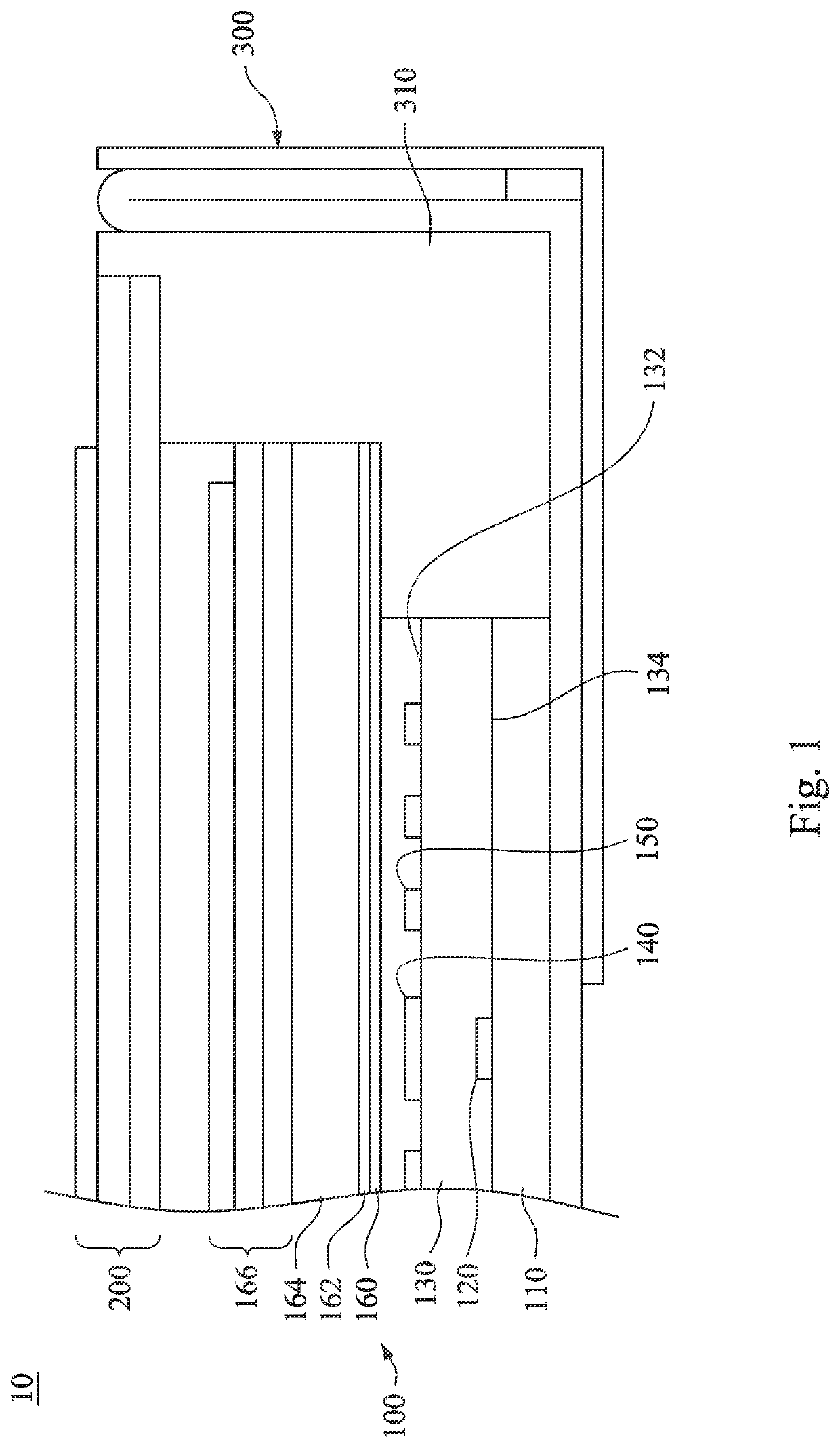
The patent provides a solution to problems with the thickness and alignment of dots in backlight modules by directly printing them onto the protective layer of the light board. This avoids the need for a diffuser plate and ensures consistent glue thickness, resulting in better screen quality. The technical effect is improved manufacturing efficiency and quality.

Problems solved by technology

As long as the alignment is slightly deviated, uneven brightness and darkness will easily occur.
However, the thinner the protective glue is, the more difficult it is to control the consistency of the thickness, resulting in uneven distribution of light and dark from the light board.

Method used


Image

  • Backlight module and display device using the same
  • Backlight module and display device using the same
  • Backlight module and display device using the same

Examples


Embodiment Construction

[0033]In the accompanying drawings, thicknesses of layers, films, panels, regions and so on are exaggerated for clarity. Throughout the specification, the same reference numerals in the accompanying drawings denote the same elements. It should be understood that when an element such as a layer, film, region or substrate is referred to as being “on” or “connected to” another element, it can be directly on or connected to the other element, or intervening elements may also be present. In contrast, when an element is referred to as being “directly on” or “directly connected to” another element, there are no intervening elements present. As used herein, the term “connected” may refer to physically connected and / or electrically connected (or coupled). Therefore, the electrical connection (or coupling) between two devices may include intervening elements existing between the two devices.

[0034]The terms used herein such as “about”, “approximate”, or “substantial” include a related value an...


PUM

PropertyMeasurementUnit
thicknessaaaaaaaaaa
sizeaaaaaaaaaa
sizeaaaaaaaaaa

Abstract

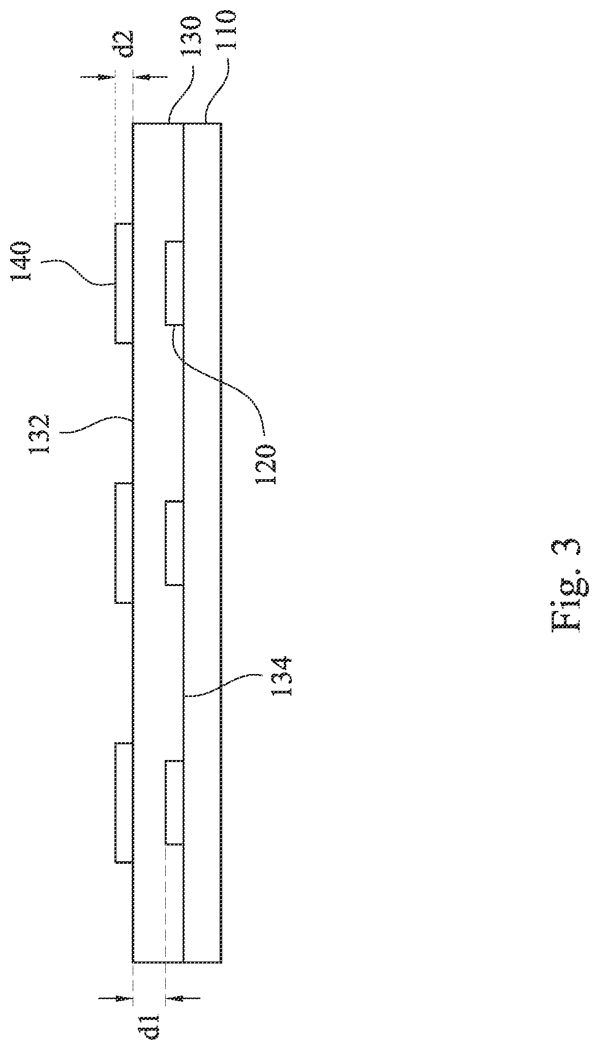
The present disclosure provides a backlight module, including a substrate, a plurality of light-emitting elements, a protective layer and a plurality of first dots. These light-emitting elements are disposed on the substrate. The protective layer is disposed on the substrate and the light-emitting elements, the protective layer has an upper surface and a lower surface opposite to the upper surface, and the upper surface of the protective layer is flat. The first dots are disposed on the upper surface of the protective layer and cover the light-emitting elements. A vertical projection area of each of the first dots on the substrate is larger than a vertical projection area of each of the light-emitting elements on the substrate, so as to reduce the thickness of the backlight module and reduce the dots alignment process.

Description

CROSS-REFERENCE TO RELATED APPLICATION[0001]This application claims priority to Taiwan Application Serial Number 109147223, filed on Dec. 31, 2020, which is herein incorporated by reference in its entirety.BACKGROUNDField of Invention[0002]The present invention relates to a backlight module and a display device.Description of Related Art[0003]Generally, most of the light-emitting element of the direct-type backlight module is light emission diode (LED). Since the light intensity directly above the LED is the strongest, dots are currently printed on the diffuser plate to reduce the light intensity directly above the LED, and to achieve the uniform brightness of the screen.[0004]With the demand for thinner and lighter products, the thickness of each component is hoped to be as thin as possible. Since the dots need to be printed on the diffuser plate currently, the thickness of the backlight module remains high. Furthermore, the diffuser plate printed with dots must be precisely aligne...

Claims


Application Information

Patent Timeline
Patent Type & Authority Applications(United States)
IPC IPC(8): F21V8/00
CPCG02B6/0093G02B6/0051G02B6/0073G02F1/133603G02F1/133606G02F1/133614G02B6/0043G02B6/0021G02B6/0068Y02B20/00
Inventor HSU, MING-CHUN
Owner AU OPTRONICS CORP
Learn More