
Method and device for manufacturing a single-layer abrasive wheel

A manufacturing method and grinding wheel technology, which are used in grinding devices, manufacturing tools, grinding/polishing equipment, etc., can solve the problem of loss of meaning in the control of the positional arrangement of single particles of abrasive grains, inconsistent benchmarks, and uneven control of the thickness of the brazing material layer. problems, to achieve the effect of improving preparation efficiency and process stability control, strong versatility, and high-quality brazing preparation

Active Publication Date: 2018-08-24
HUAQIAO UNIVERSITY
View PDF5 Cites 0 Cited by
  • Summary
  • Abstract
  • Description
  • Claims
  • Application Information

AI Technical Summary

Problems solved by technology

One of the root causes of this problem is that the clamping datum of the grinding wheel in the production process is inconsistent with the datum on the machine tool spindle when the grinding wheel is used, and the machining error of the inner hole of the grinding wheel and the positioning axis
The objective existence of these reasons leads to uneven control of the thickness of the solder layer in the process of brazing the grinding wheel
On the other hand, as the particle size of the abrasive particles becomes smaller, the control of the single particle position of the abrasive particles becomes meaningless. How to prevent a large amount of abrasives from agglomerating during the coating and sanding process, and how to control the concentration has become an urgent problem in the field of preparation.

Method used


Image

  • Method and device for manufacturing a single-layer abrasive wheel
  • Method and device for manufacturing a single-layer abrasive wheel
  • Method and device for manufacturing a single-layer abrasive wheel

Examples


Embodiment 1

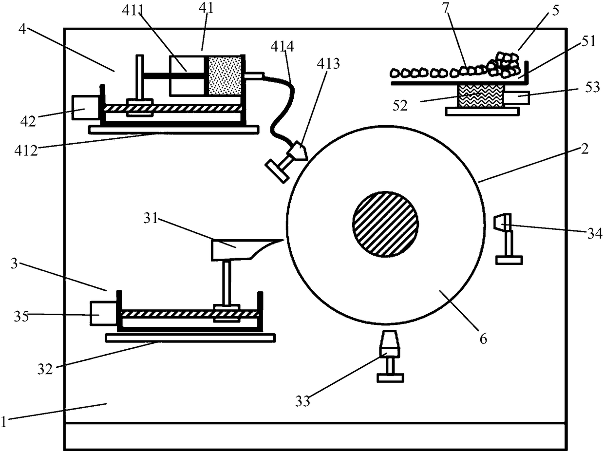
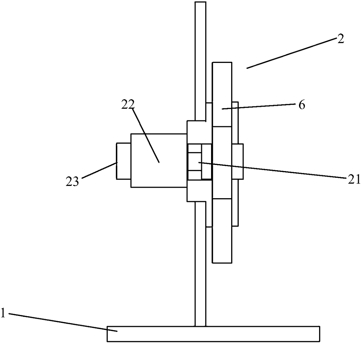
[0041] like figure 1 and figure 2 As shown, a manufacturing device of a single-layer abrasive wheel includes a base 1, a data processing control assembly (not shown in the figure) and a rotating assembly 2 and a certain thickness assembly 3 arranged on the base 1 , a bonding agent coating assembly 4 and an abrasive particle sprinkle assembly 5 .

[0042]The rotating assembly 2 includes a rotating shaft 21, a driving motor 22 and a rotational motion control unit 23, the rotating shaft 21 drives the grinding wheel base 6 to rotate perpendicular to the horizontal plane under the drive of the driving motor 22, and the rotational motion control unit 23 is electrically connected to the driving motor 22 , to control the drive motor 22 to run at different speeds;

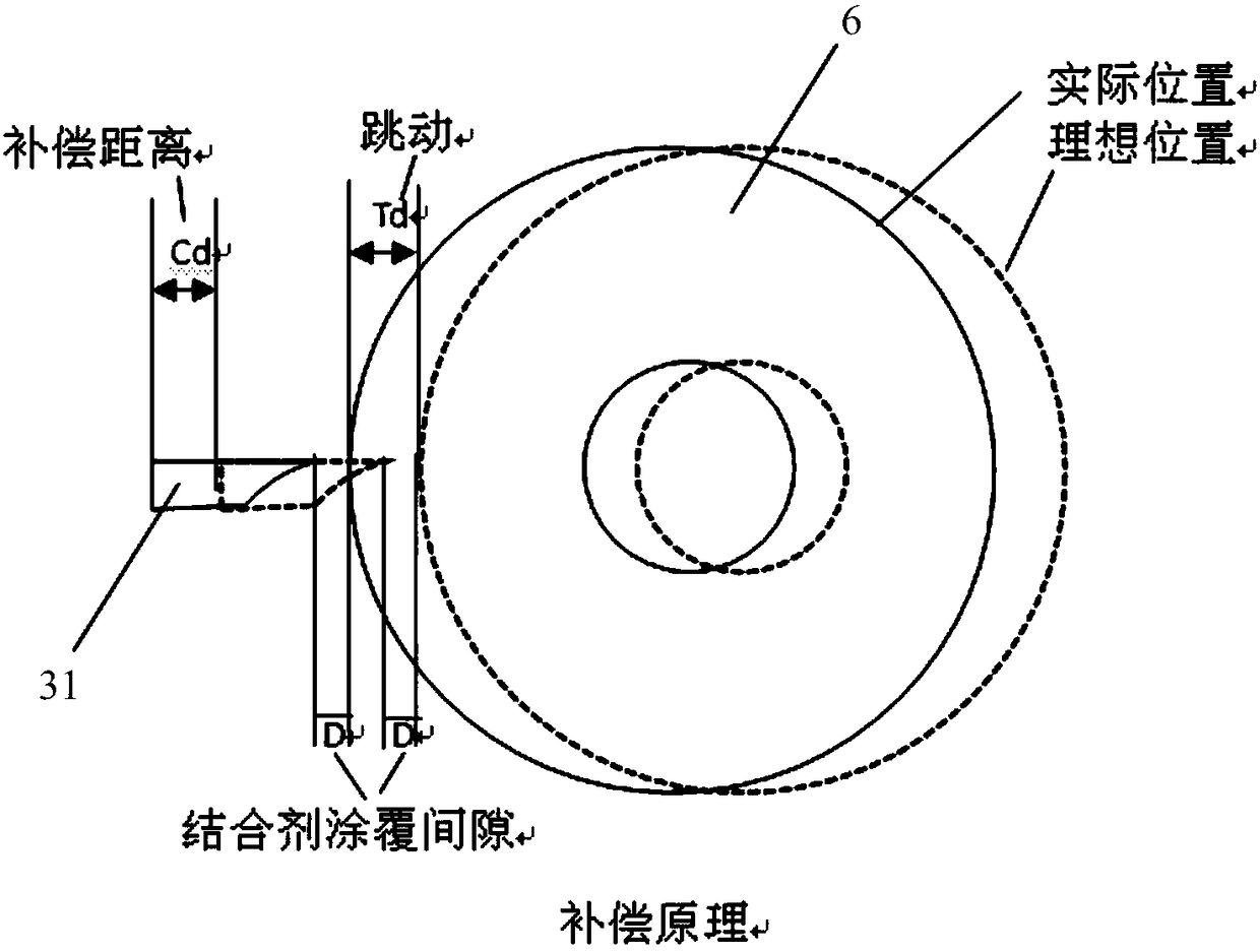
[0043] The thickness-fixing assembly 3 includes a certain thickness plate 31, a first uniaxial reciprocating mechanism 32, a displacement sensor 33, an angle sensor 34 and a runout data acquisition analysis and compensat...


PUM


Abstract

The invention discloses a manufacturing method and device for a single-layer abrasive particle grinding wheel. The method includes the following steps that firstly, a fixed-thickness structure is adjusted so that an unchangeable binding agent coating gap can be formed by the fixed-thickness structure and a to-be-coated work face of a grinding wheel base body; secondly, the to-be-coated work face of the rotating grinding wheel base body is coated with a binding agent, the binding agent is smeared to the whole grinding wheel base body through the rotation movement of the grinding wheel base body, meanwhile, the excessive binding agent smeared to the surface of the grinding wheel is spread and removed through the fixed-thickness structure under the restraint of the binding agent coating gap between the fixed-thickness structure and the grinding wheel base body; thirdly, after the binding agent is smeared, the grinding wheel base body rotates continuously, abrasive particles fall at a uniform speed from the fixed position above the grinding wheel base body, and the abrasive particles can be evenly scattered on the surface of the binding agent of the grinding wheel base body by means of the rotation movement of the grinding wheel base body; and fourthly, binding agent curing is conducted on the grinding wheel base body coated with the binding agent and the abrasive particles, and the brazing abrasive particle grinding wheel is formed.

Description

technical field [0001] The invention belongs to the field of abrasive tool preparation, and in particular relates to a method and device for manufacturing a single-layer abrasive wheel. Background technique [0002] Due to the excellent physical and mechanical properties of abrasive grains such as high hardness, abrasive grain grinding wheels have become a key means of forming parts and forming high-quality surfaces with their excellent grinding characteristics such as high efficiency, stability, and durability. They are used in metals, engineering ceramics, optical crystals, High-efficiency and precision grinding of semiconductors and natural rocks, cemented carbide, optical crystals, engineering ceramics, aerospace titanium alloys and other materials play an irreplaceable role as a pillar. [0003] The key to achieving material removal with abrasive grinding wheels is to use the abrasive grains consolidated on the surface of the grinding wheel to remove the workpiece mater...

Claims


Application Information

Patent Timeline
Patent Type & Authority Patents(China)
IPC IPC(8): B24D18/00
CPCB24D18/0072
Inventor 黄国钦陈世隐余凯峰穆德魁黄辉郭桦徐西鹏
Owner HUAQIAO UNIVERSITY
Learn More