Method for detecting a cell event

Pending Publication Date: 2022-06-16
COMMISSARIAT A LENERGIE ATOMIQUE ET AUX ENERGIES ALTERNATIVES
View PDF0 Cites 0 Cited by
  • Summary
  • Abstract
  • Description
  • Claims
  • Application Information

AI Technical Summary

Benefits of technology

The invention relates to a method and device for detecting or predicting the occurrence of a cell event in a sample. The method involves using a light source and an image sensor to capture images of the sample, and analyzing the images to detect changes in optical path difference or absorbance caused by the cells. This change can be used to predict the location and time of the cell event. The device includes a light source, an image sensor, and a support for holding the sample between the light source and image sensor. The technical effects of this invention include improved accuracy in detecting and predicting cell events, as well as improved efficiency and accuracy in analyzing cell behavior.

Problems solved by technology

In microscopy, however, the observation field is restricted because of the high magnification imparted by the objectives with which microscopes are equipped.
A difficulty may arise when there is a sample, comprising numerous cells, extending over a surface larger than the observation field of a microscope.
If the intention is to obtain a sufficient observation statistic, it is difficult to observe different parts of the same sample simultaneously, even more so since mitoses occur at random instants.

Method used


Image

  • Method for detecting a cell event
  • Method for detecting a cell event
  • Method for detecting a cell event

Examples


Embodiment Construction

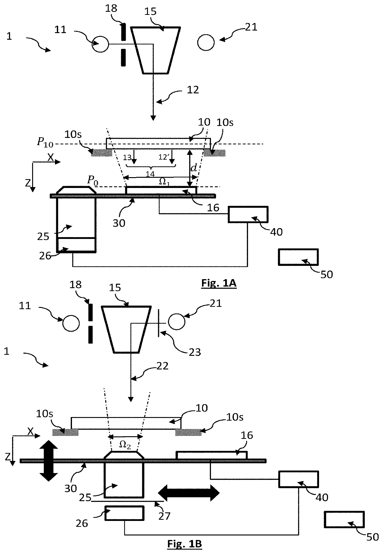
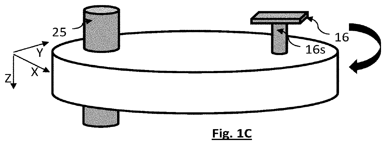
[0068]FIGS. 1A, 1B and 1C represent an example of a device 1 for observing a sample, making it possible to carry out the invention. It is a device making it possible to observe a sample according to a lensless first imaging mode and a second mode of conventional imaging, with focused imaging, by using an objective making it possible to obtain a magnification of the image. The observation device is based on the dual-mode device described in EP3519899A1 (U.S. Ser. No. 10 / 754,141), which was cited in the prior art. FIG. 1A represents the device configured according to the lensless imaging mode, whereas FIG. 1B shows the device configured according to a focused microscopy mode, for example with fluorescence imaging.

[0069]The device comprises a first light source 11 capable of emitting a first light wave 12, referred to as the incident light wave, which propagates towards a sample 10 along a propagation axis Z, in a first spectral band Δλ.

[0070]The sample 10 is arranged on a sample suppo...


PUM


Abstract

Method for detecting or predicting the occurrence of a cell event, selected from between cell division or cell death, in a sample (10), the sample extending in at least one sample plane (P10) and comprising cells (10p) immersed in a medium, the method comprising the following steps:a) arranging the sample between a light source (11) and an image sensor (16);b) illuminating the sample (10) using the light source (11) and acquiring a plurality of successive images ((Ii(ti), I1(ti+1) . . . I1(ti+K)) of the sample at different instants ([ti; ti+K]) forming an acquisition time range, each image being representative of an exposure light wave to which the image sensor is exposed;c) on the basis of each acquired image of the sample, calculating an observation image at each instant (I10(ti), I10(ti+1) . . . I10(ti+K)), the observation image corresponding to a spatial distribution of an optical path difference induced by the cells, or of an absorbance of the cells, in the sample plane (P10);d) using the observation images resulting from c) as input data of a supervised artificial intelligence algorithm (CNNd, CNNp), so as to predict or locate an occurrence of the cell event.

Description

TECHNICAL FIELD[0001]The technical field of the invention is the observation of a cell event, in particular cell division or cell death, with the aid of optical detection means.PRIOR ART[0002]The observation of cells is frequently confronted with the detection of events affecting the life of the cells, in particular cell division (mitosis or meiosis) or cell death.[0003]Mitosis is a complex cell division process which is still the subject of in-depth studies. This is because the observation of mitoses is an important element for the study of pathologies involving misregulation of cell division, in particular cancer.[0004]At present, mitoses are generally observed by microscopy, whether fluorescence microscopy, standard microscopy, by using a coloured marker, or phase contrast microscopy. In microscopy, however, the observation field is restricted because of the high magnification imparted by the objectives with which microscopes are equipped.[0005]It may also be necessary to monitor...

Claims


Application Information

Patent Timeline
IPC IPC(8): G06T7/00G06K9/20
CPCG06T7/0016G06K9/2054G06T2207/30024G06T2207/20084G06T2207/20081G06T2207/10148G06V20/69G06V10/764G06V10/82G06V10/22
Inventor ALLIER, CÉDRICKRÄMER, DOROTHÉEHERVE, LIONEL
Owner COMMISSARIAT A LENERGIE ATOMIQUE ET AUX ENERGIES ALTERNATIVES
Why Eureka
Try Eureka