Flow rate sensor system, method for and use of such system for determining a flow rate

a flow rate sensor and flow rate technology, applied in the field of sensing fluid movement, can solve problems such as rising costs at the customer's end

Pending Publication Date: 2022-06-02
ROCHE MOLECULAR SYST INC
View PDF0 Cites 1 Cited by
  • Summary
  • Abstract
  • Description
  • Claims
  • Application Information

AI Technical Summary

Problems solved by technology

These problems generally lead to rising costs at the customer's end, and respectively generated er

Method used


Image

  • Flow rate sensor system, method for and use of such system for determining a flow rate
  • Flow rate sensor system, method for and use of such system for determining a flow rate
  • Flow rate sensor system, method for and use of such system for determining a flow rate

Examples


first embodiment

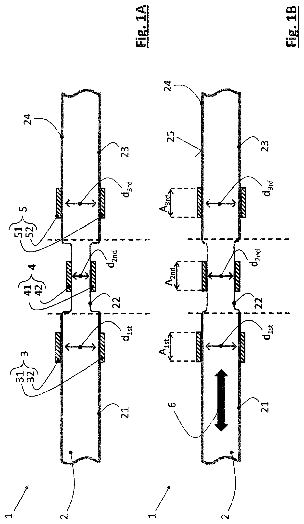
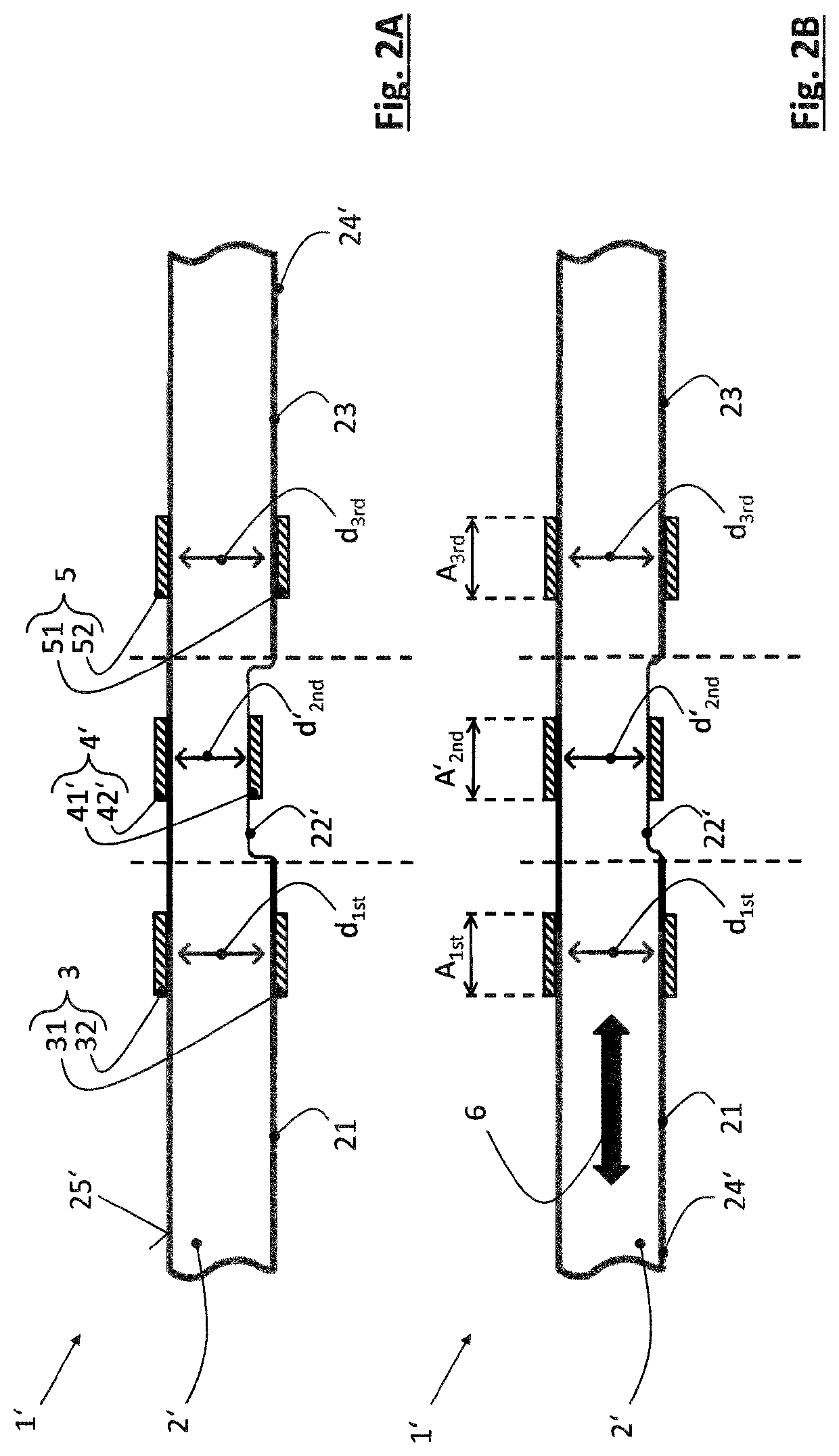
[0080]FIGS. 1A and 1B show a part of a sensor system 1 according to the present disclosure. Here, it is pointed out that a sensor unit and a processing unit in general being part of the sensor system 1 of the present disclosure are not illustrated in the drawings for the sake of simplification. However, it is to be noted that the sensor unit and the processing unit are interconnected and are connected to the respective electrodes of the sensor system 1. Now, the shown part of the sensor system 1 comprises a tubular fluid channel 2 and a first pair 3 of electrodes 31, 32 at a rigid segment 21 of the fluid channel 2, with the electrodes 31, 32 being fixed with respect to each other and attached to, e.g. printed onto, an outer circumference 25 of a wall 24 of the fluid channel 2 at the rigid segment 21. Furthermore, the sensor system 1 comprises a second pair 4 of electrodes 41, 42 at an elastic segment 22 of the fluid channel 2, with the electrodes 41, 42 being arranged in a moveable ...

third embodiment

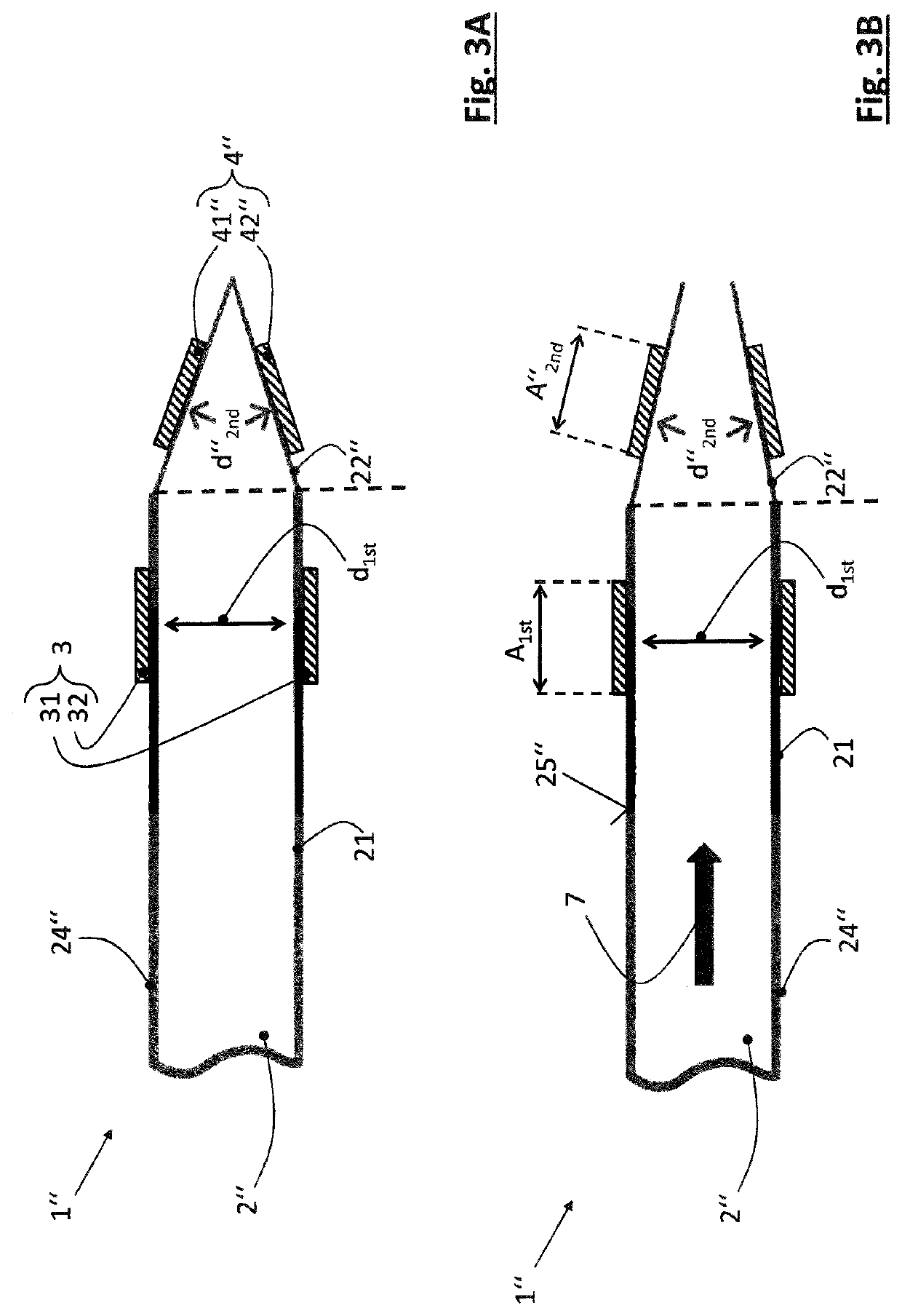
[0092]In accordance with the opening of the closed end of the elastic segment 22″, the flow 7 of the fluid within the fluid channel 2″ can be measured through change of capacitance of the electrode pair 4″ caused by the change in distance between these electrodes 41″, 42″ due to the angle-widening movement of the elastic segment 22″. This change in distance is again allowed by elastic deformation of the elastic segment 22″ caused by an increase of fluid pressure of the fluid flowing within the fluid channel 2″. In the presently described third embodiment, no further electrode pair is used, contrary to the previously described embodiments. Accordingly, in FIGS. 3A and 3B, the part of the fluid channel 2″ show in these illustrations comprises the first rigid segment 21 and the nozzle-like elastic segment 22″, wherein a transition area between those segments is again implemented without substantial interruption, and the wall 24″ of the fluid channel 2″ is substantially continuous, in p...


PUM


Abstract

The present disclosure provides for a sensor system for determining a flow rate of a fluid flow within a fluid channel comprising an elastic segment arranged next to a rigid segment, wherein a first pair of electrodes is provided at the rigid segment and a second pair of electrodes is provided at the elastic segment of the fluid channel. The system further comprises a sensor unit for detecting a capacitance of the first and second electrode pairs, and a processing unit for calculating and monitoring a distance between the electrodes of the second electrode pair based on the detected capacitance of the first electrode pair and the second electrode pair, wherein the first electrode pair is in contact with the rigid segment and the second electrode pair is in contact with the elastic segment. Moreover, a respective method for determining a flow rate of a fluid flow within a fluid channel is provided by the present disclosure, as well as a use of the sensor system.

Description

CROSS-REFERENCE TO RELATED APPLICATION[0001]This application claims the benefit and priority of European Application Serial No. 20210683.7, filed Nov. 30, 2020, the contents of which are incorporated herein by reference for all purposes.TECHNICAL FIELD[0002]Generally, the present disclosure relates to the technical field of sensing fluid movement in a flexible fluid channel, and in particular to determining a flow rate in such a fluid channel based on an expansion of the fluid channel.[0003]In particular, the present disclosure is directed to a flow rate sensor system for sensing or detecting the movement of a fluid in a fluid channel, and in more detail to a system for determining a flow rate of the fluid in the fluid channel, wherein capacitive expansion measurement is carried out in order to measure a respective capacitance change due to expansion of the fluid channel and, based thereon, determine a fluid flow rate in the fluid channel. The present disclosure is further directed ...

Claims


Application Information

Patent Timeline
IPC IPC(8): G01F1/58
CPCG01F1/584G01F1/64
Inventor EBERT, SVENDOBRZYNSKI, MICHAL KAROLFEDERER, PAULSTAIB, ARNULFSCHNEIDER, LUKAS
Owner ROCHE MOLECULAR SYST INC
Why Eureka
Try Eureka