System for recovering natural gas liquid from low pressure source at low temperatures

Pending Publication Date: 2022-05-19
NGLTECH
View PDF0 Cites 0 Cited by
  • Summary
  • Abstract
  • Description
  • Claims
  • Application Information

AI Technical Summary

Benefits of technology

The patent describes a system for separating liquid from gas in a cooling process. The system includes a compressor to increase the temperature and pressure of the gas from a gas source, a separator to direct the gas to expansion means to reduce the pressure and temperature of the gas, and a cooling unit to remove the cold energy from the gas. The system also includes an antifreeze agent to prevent blockages and self-regenerates within the system. The use of the antifreeze agent and the position of the expansion means downstream of the separator improves the efficiency of the cold separator and increases the recovery of liquid evaporant. This results in more effective and efficient separation of gas and liquid from high-quality gas sources.

Problems solved by technology

Low pressure hydrocarbon gases particularly associated gas from oil and gas production facilities pose significant challenges for operators worldwide as typically the facilities are stranded with lack of infrastructure to route the produced gas.
In addition, being at low pressure, the cost associated with the additional compression facilities very often makes it uneconomical to monetize the gas.
Decline in well pressures of mature fields also makes it challenging to install additional compression facilities to boost pressure of produced gas.
However, if the raw feed gas pressure is low, condensate recovery is poor due to the small change in pressure achievable and hence the low JT effect.
Mechanical refrigeration system however are bulky and expensive which includes compression equipment and power consumption.
However, these systems require some amount of pre-treatment to protect the membranes and compression of the permeate stream to minimize NGL losses.
In addition, to be economically viable, these systems require relatively high inlet gas pressures.
As can be seen from the preceding discussions, whilst there are many NGL recovery systems by means of various types of HCDPC units, these are only really suitable for feed gas streams that operate at relatively high pressures.
In addition, the refrigeration systems that can handle low pressure feed gas streams, are very bulky, complex and costly, making them economically not viable for many low pressure applications.
In many cases, the associated gas is an undesirable by-product that is utilized as fuel gas with the balance flared, along with valuable NGLs as it is un-economical to extract.NGLs are an excellent enhanced oil recovery (EOR) solvent.
However, the cost of extracting NGLs from low pressure associated gas makes this option for EOR not viable in many cases.Non-associated gas production reservoirs in many cases are abandoned when flowing pressures decline below 10 barg as it becomes uneconomical.Low pressure off-gas from various sources like the refinery or Petrochemicals Complex in many cases are either used as fuel gas or flared.
Apart from the environmental impact of venting, there is significant revenue loss due to shrinkage of crude volumes due to these vaporization losses.
Ironically though, it is the low pressure natural gas streams that are typically disposed as fuel gas or flared as is uneconomical to recover.
However, at operating pressures below the cricondentherm, the temperature and / or pressure may have to be reduced more significantly to cause liquid drop-out (required for the separator to work), but as a result hydrates may form and cause blockages.

Method used


Image

  • System for recovering natural gas liquid from low pressure source at low temperatures
  • System for recovering natural gas liquid from low pressure source at low temperatures
  • System for recovering natural gas liquid from low pressure source at low temperatures

Examples


Embodiment Construction

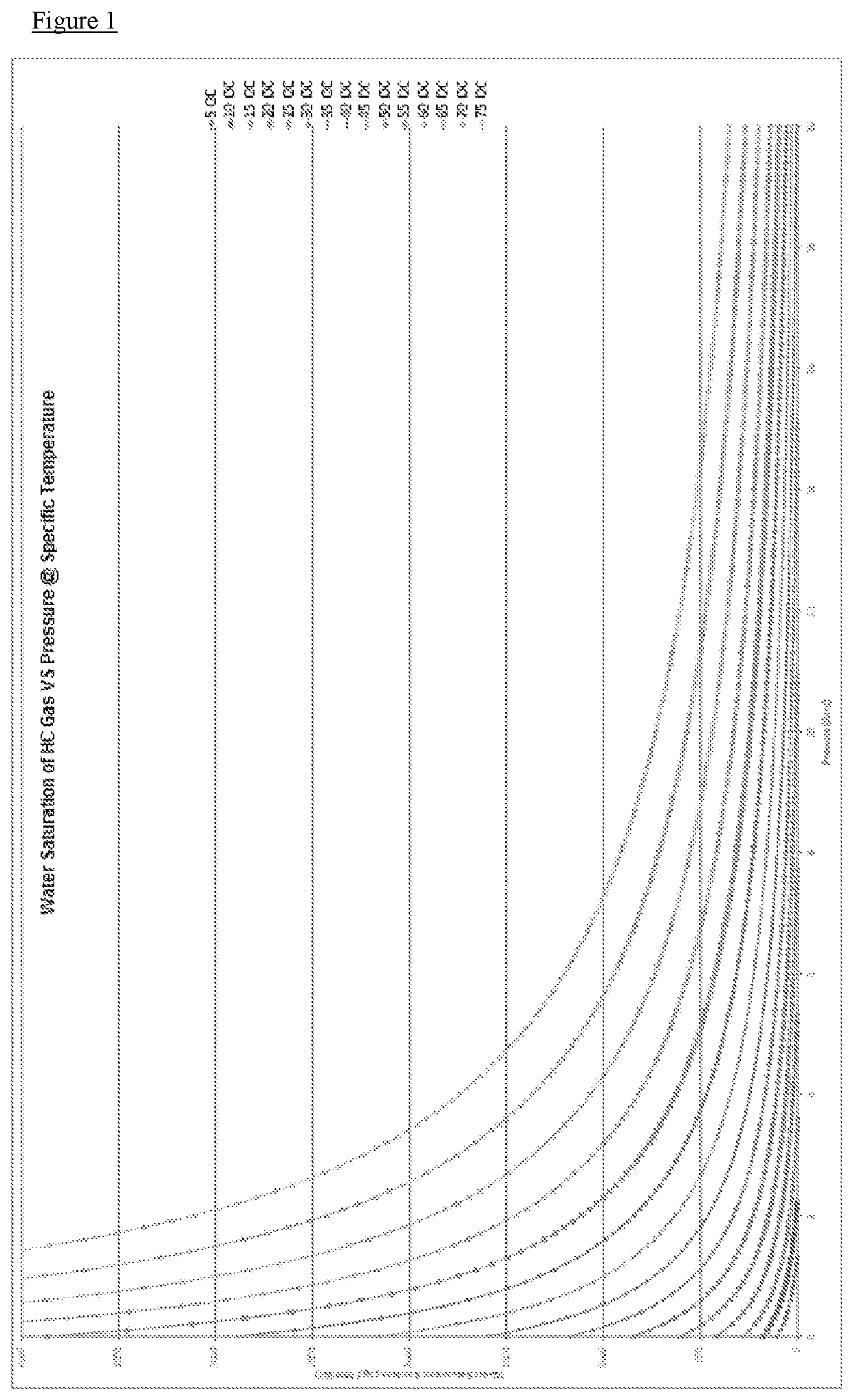
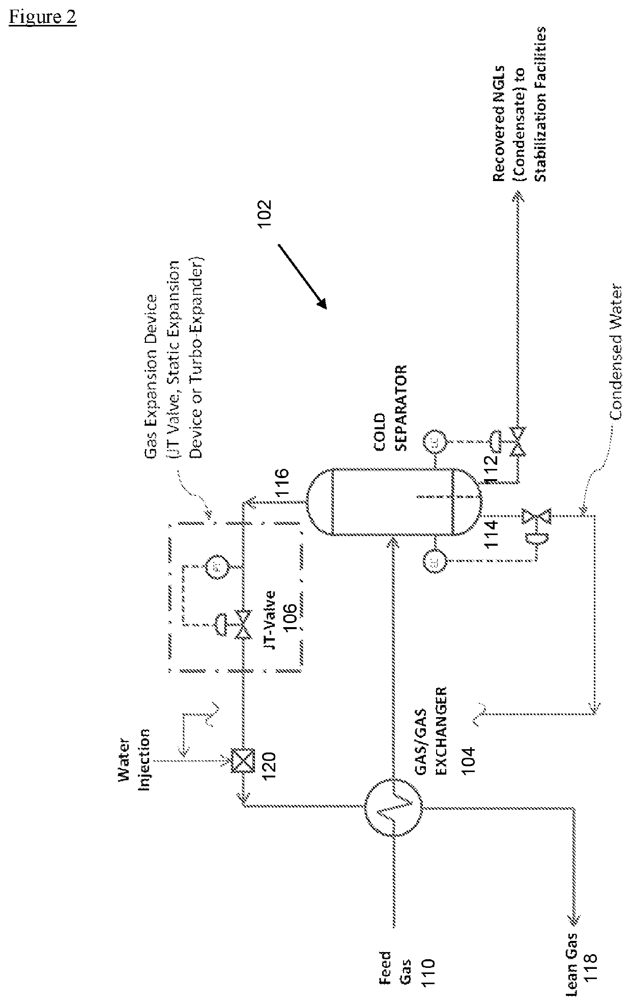
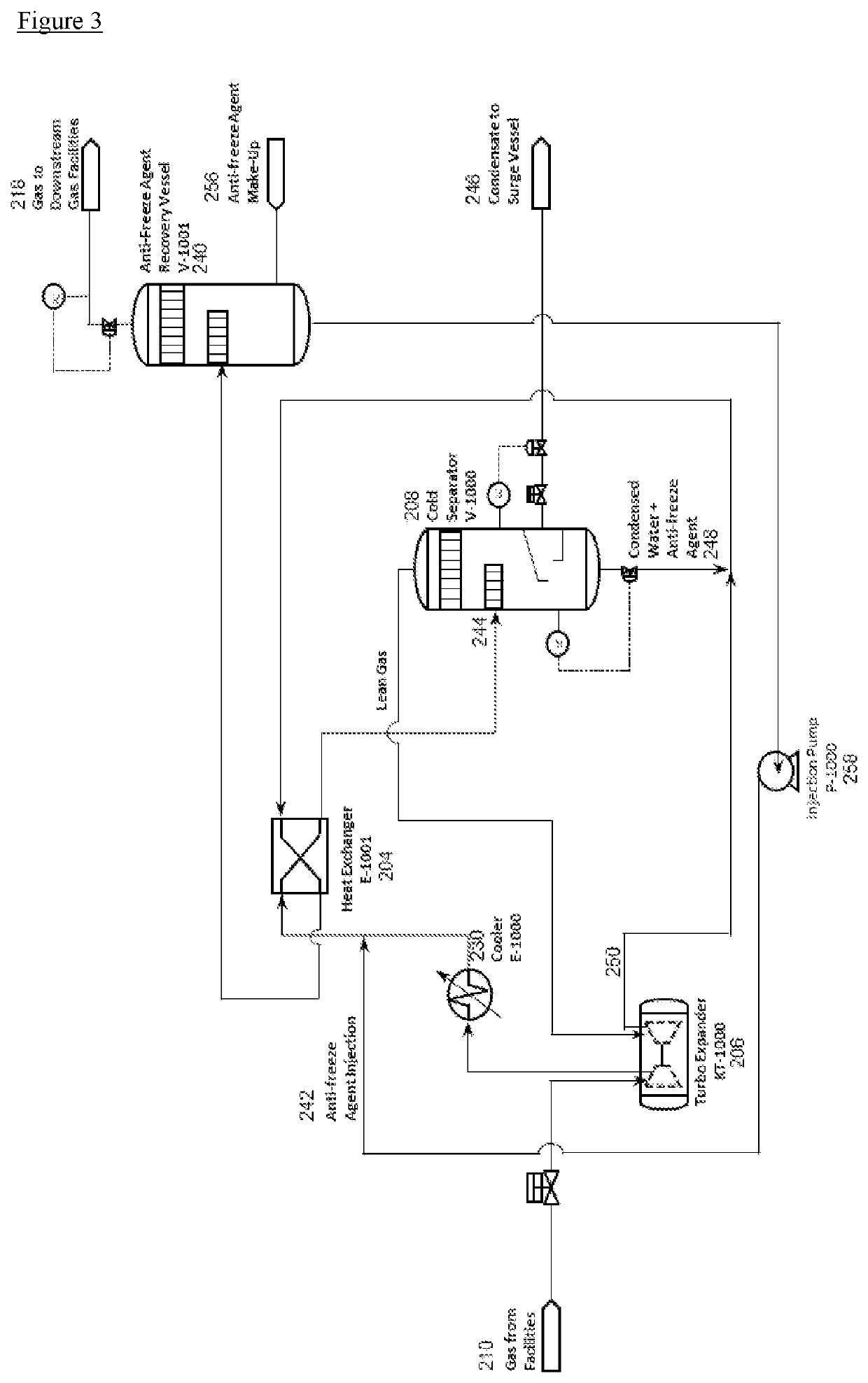
[0066]Hydrocarbon Dew Point Control (HCDPC) of low pressure gas uses the concept of evaporative cooling, coupled with a gas expansion device which may either be a JT Valve, Static Expansion Devices or a Turbo-Expander, to chill the gas stream to condense and remove the heavier hydrocarbon components (NGLs) from the natural gas stream.

[0067]Evaporative cooling is the addition of water vapor into gas that is water dew pointed, which causes lowering the temperature of the gas. The energy needed to evaporate the water is taken from the gas in the form of sensible heat, which reduces the temperature of the gas, and converted into latent heat, the energy present in the water vapor component of the gas, whilst the gas remains at a constant enthalpy value. This conversion of sensible heat to latent heat is known as an adiabatic process because it occurs at a constant enthalpy value. Evaporative cooling therefore causes a drop in the temperature of gas proportional to the sensible heat drop ...


PUM


Abstract

A system for recovering natural gas liquid from a gas source, comprising compression means (206) for increasing the temperature and pressure of the fluid from the gas source, cooling means (230) for cooling the fluid from the compression means, a gas / gas heat exchanger (204), fluid from the gas source flowing from a first inlet to a first outlet; at least one separator (208) for receiving the fluid from the first outlet of the gas / gas heat exchanger (204) and separating liquid from the gas, the gas from the separator being directed to expansion means (206) for reducing the temperature and pressure of the gas, the aqueous part of the liquid from the separator and / or the gas from the expansion means being directed to the gas / gas heat exchanger (204) where it flows therethrough from a second inlet to a second outlet for cooling the fluid flowing between the first inlet and first outlet, wherein injection means are provided between the cooling means and the gas / gas heat exchanger for saturating the gas with a liquid agent, wherein the liquid agent comprises an evaporant and an antifreeze agent; and a recovery vessel (240) is provided downstream of the second outlet, the antifreeze agent being recovered therein for injection into the fluid from the gas source upstream of the first inlet.

Description

FIELD OF INVENTION[0001]The invention relates to a system for recovering natural gas liquid from a low pressure source at low temperatures.BACKGROUND[0002]A natural gas stream often contains light hydrocarbons. Natural gas liquids (NGL) is the general term for liquids extracted from the natural gas stream (ethane and heavier products) and within this liquefied petroleum gas (LPG) is the term used to refer to extracted liquids where the main components are propane, n-butane and iso-butane.[0003]Low pressure hydrocarbon gases particularly associated gas from oil and gas production facilities pose significant challenges for operators worldwide as typically the facilities are stranded with lack of infrastructure to route the produced gas. In addition, being at low pressure, the cost associated with the additional compression facilities very often makes it uneconomical to monetize the gas. Decline in well pressures of mature fields also makes it challenging to install additional compress...

Claims


Application Information

Patent Timeline
IPC IPC(8): C10G5/06C10L3/10
CPCC10G5/06C10L3/107C10L3/101C10L2290/46C10L2290/10C10L2290/545C10L2290/08C10L2290/141C10L2290/48C10L2290/04C10L2290/12C10L3/10C10L2290/14C10L2290/54C10L2290/543
Inventor A/L SUPPIAH, ARUL JOTHYOOI, BOON LEECHEN, CHING LIANGEISA FARAG, EBTEHAL EISA REGHEBA/L TURUNAWARASU, DHANARAJ
Owner NGLTECH
Why Eureka
Try Eureka