
Self-trailering grain bagging machine on four wheels

a grain bagging machine and self-trailing technology, applied in the field of grain bagging machines, can solve the problems of placing undue weight on the tractor or vehicle, and achieve the effect of optimizing labor and enhancing overall braking effectiveness

Pending Publication Date: 2022-05-19
RICHIGER GABRIEL ALBERTO
View PDF37 Cites 0 Cited by
  • Summary
  • Abstract
  • Description
  • Claims
  • Application Information

AI Technical Summary

Benefits of technology

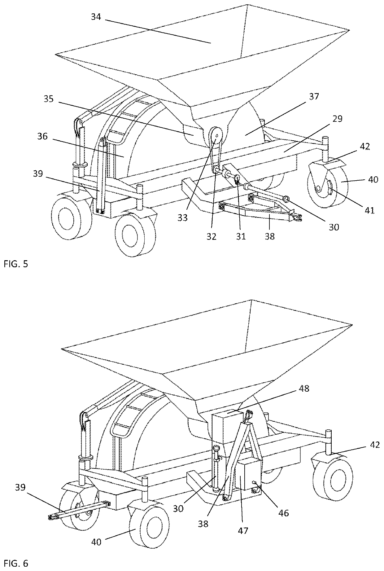
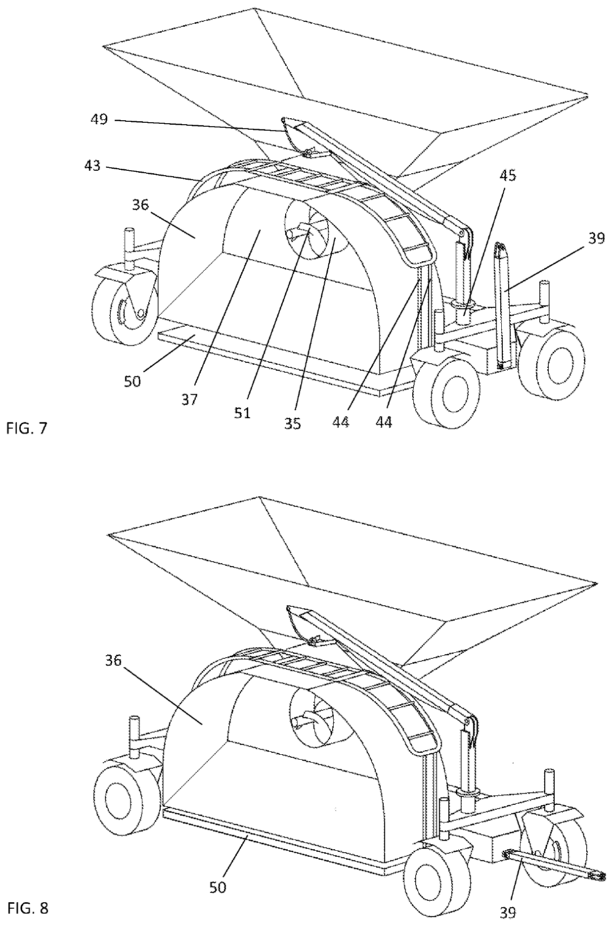
The present patent suggests a four-wheel arrangement for grain baggers that offers better stability, ease of switching between work and transport, the option of using a smaller powered tractor for work and a lighter vehicle for towing, simplifies mounting the silo bag on the grain bagger tunnel, and forestalls physical risks to operators that originate from traditional grain baggers supported by two wheels. The technical effects of the patent are improved safety standards, better performance and efficiency in various conditions, and improved user experience.

Problems solved by technology

This may place undue weight on tractor or vehicle.

Method used


Image

  • Self-trailering grain bagging machine on four wheels
  • Self-trailering grain bagging machine on four wheels
  • Self-trailering grain bagging machine on four wheels

Examples


example b

[0028]When bagging on a slope, tractor and bagger may not be able to operate transversally across it and be restricted to running either up or down the gradient. If running upward, the weight of the machines will normally help to compact the material, but if slope angle is excessive it can produce too much compaction in the bag even without applying brakes. In such circumstances and being forced to run downward, the situation is reversed and very efficient braking action will be required to compact the material adequately, in which case four wheels will perform better than two.

example c

[0029]Even when bagging under normal conditions over firm terrain, braking power distributed among more brakes can optimize labors. Sometimes the bagger brakes are set to apply high pressure on the discs in order to pack the grain more firmly, causing the brakes to seize up when brake calipers press so hard against the brake discs that these don't turn. This often results in short lapses in which the wheels do not rotate and tractor and bagger do not advance while the bag continues to expand as the compression screw keeps pushing grain in. As pressure mounts inside the bag, the pent-up energy abruptly overcomes brake resistance and then the tractor / bagger combo jumps forward, whereupon the cycle iterates. These intermittent cycles create humps on the bag's top section that reflect spots of higher and lower compaction. In a worst case scenario, if brakes remain stuck the incoming grain can very rapidly cause bag rupture and material loss. In the present disclosure this unwanted effec...


PUM


Abstract

A self-trailering grain bagging machine on four wheels for storing grains and seeds inside a silo bag. The machine has a grain receiving hopper within which a compression auger encased in an auger tube. The auger is driven by mechanical means powered from a tractor's power take-off. The machine is mounted on a frame fitted with paired crossmembers at its left and right hand sides. Each crossmember is mounted upon a pair of wheel supports. The wheel supports are capable of gyrating relative to the crossmembers. The wheel supports carry one wheel that wheel rotates along with said wheel support. A work tongue is attached to the front side of the frame. The work tongue pivots relative to a horizontal axis. A transport tongue is attached to one crossmember wherein the wheels remain aligned in the direction intended for work and when turning said wheel supports by 90 degrees.

Description

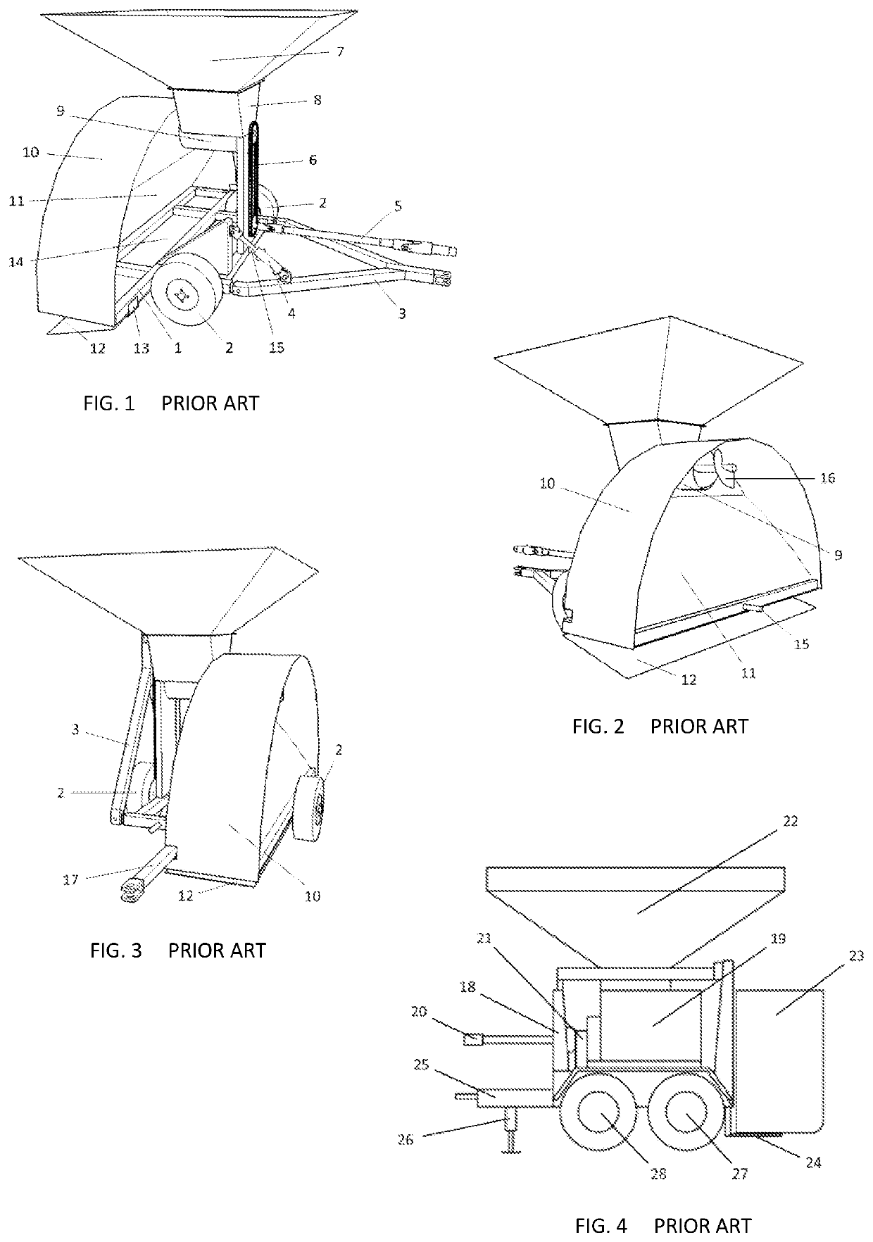
BACKGROUNDPrior Art[0001]Whole Grain Bagging Machines[0002]The present specification refers to grain bagging machines, or more specifically to whole grain baggers. Throughout the disclosure they will often be referred to simply as baggers. These are employed to store different kinds of grains and seeds in large, elongated plastic bags for short to long term preservation. These are usually called silo bags or bags in a shortened form and usually consist of three layers of high density polyethylene that provide great elasticity and resistance.[0003]Whole grain baggers can store other types of organic or inorganic materials, as for instance dry sand, the requisite condition being that these materials can run more or less freely, i.e. that they can flow to a certain degree.[0004]Baggers typically range from 6 ft to 12 ft models, meaning that depending on the model they can fill bags that go from 6 ft (approx. 1.80 m) to 12 ft (approx. 3.60 m) in diameter, with lengths that usually vary ...

Claims


Application Information

Patent Timeline
Patent Type & Authority Applications(United States)
IPC IPC(8): A01F25/14B62D63/08B66C23/36
CPCA01F25/14B62D63/08B66C23/54A01F2025/145B66C23/36B60S9/10
Inventor RICHIGER, GABRIEL ALBERTO
Owner RICHIGER GABRIEL ALBERTO
Learn More