Ankle orthosis

a technology for ankles and bones, applied in the field of ankle bones, can solve the problems of recurrent instability and associated defects, largely underreported sprains, and unable to meet the needs of patients, and achieve the effects of low cost, high efficiency, and high efficiency

Active Publication Date: 2022-03-17
ICARUS MEDICAL LLC
View PDF0 Cites 1 Cited by
  • Summary
  • Abstract
  • Description
  • Claims
  • Application Information

AI Technical Summary

Benefits of technology

The device described in this patent is a customizable ankle orthosis that can control the movement of the ankle joint. The device has several features including a tensioning or compression apparatus, a mechanism for changing the direction or orientation of corrective force, and a method to custom-fabricate the shape or form of the device to the user's anatomy to optimize comfort and efficacy. In some embodiments, the ankle orthosis is designed to limit motion in a specific direction to prevent over or counter rotation of the ankle joint. In other embodiments, the brace allows mobility within certain axes while limiting it in others to provide only the necessary directional stability. Overall, the device allows for greater freedom of the joint while providing necessary stability.

Problems solved by technology

Due to self-treatment, sprains are largely underreported because most patients never visit a clinic or professional.
While this injury may seem temporary to the individual at the time of the sprain, it presents serious long-term implications.
While most ankle sprains are successfully managed with nonoperative modalities, recurrent instability and associated defects can be seen in 25-40% of patients, which only accounts for those reported in a largely unreported field.
The condition ultimately leads to insufficiency of the lateral ankle ligament complex.
This negatively alters central mechanisms of motor control, leading to an increased risk of falls, and is a leading cause of post-traumatic ankle joint osteoarthritis.
Ultimately, a single sprain may result in a significantly reduced quality of life, which is associated with increased mortality due to comorbidities such as heart disease, stroke, depression and diabetes.
While the indications facing the ankle joint are varied, numerous, and prevalent, there is a lack of personalized solutions.
While the procedure may reduce pain within the joint in the short term by eliminating the articulation of arthritic surfaces, the procedure presents lasting challenges including lack of mobility of the ankle, reduced stability, and reduced function.
Additionally, the changes to the individual's gait due to reduced joint flexibility lead to adverse biomechanical forces in other joints of the lower body including the knee, hip, and back.
As a result, the individual's overall mobility health and long-term quality of life declines.
While this avoids the cost associated with fusion surgery, these braces are less effective, yield mixed opinions between prescribers as to whether they are effective or not, present the same problems in limiting mobility in all axes of the joint, and do not present a personalized solution to the unique needs of the individual.
Although current braces may be able to address specific indications and limit movement to prevent further injury and / or support recovery while activity is maintained, they are often bulky, rigid, and not customized to address the user's specific deficiency or need.
Additionally, they are often static devices that are not adjustable by the user or clinician to best address the user's need, desired activity or state of movement.
While these braces do have an adjustable strap, they do not offer a method for adjusting tension to control rotation around the ankle.
Furthermore, this brace only allows movement along one axis allowing plantar- and dorsiflexion.
This device is used only for the pediatric market for strengthening, as the device is not designed to address conditions such as foot drop, ankle osteoarthritis, ankle instability or other common indications.
Additionally, the design is limited to a low-power elastic band, which is insufficient to support the range forces required to address a range of indications and patient populations beyond pediatric strengthening.
Unlike the multi-axis rotation control brace described herein, this application does not demonstrate adjustability of the direction of force, or application of the mechanism for conditions beyond foot drop.
In other words, the device cannot be tailored by a clinician or the user based on the specific direction and magnitude of force required for the user.
The same limitations apply to an on-market technology, the SaeboStep® brace.
The device is further limited, as it is not custom (off-the-shelf or one size fits all) and is not personalized to the user's need, as described in the multi-axis rotation control brace described herein.

Method used


Image

  • Ankle orthosis
  • Ankle orthosis
  • Ankle orthosis

Examples


examples

Preferred Embodiment One: Multi-Axis Rotation Control Ankle Brace with Proximal and Distal Portions and Hinge

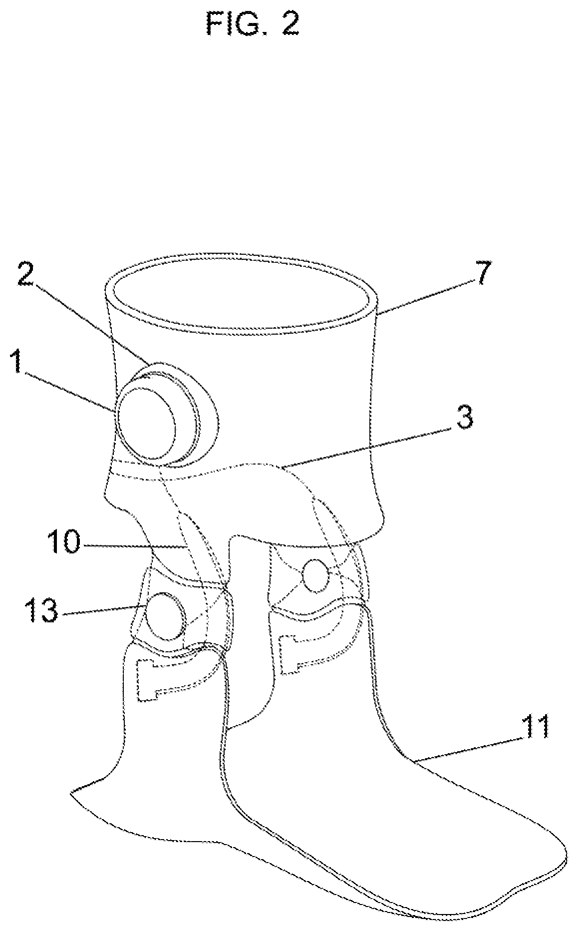
[0057]Preferred embodiment one (FIG. 2) is comprised of a proximal cuff (7) and distal portion (11) connected by a hinge (13). The device contains an adjustable tensioning apparatus (3,9,10) that runs across the one or more hinge that is positioned medial and / or lateral to the ankle joint. The tensioning element in this case represents one type of energy storage element, in this case under tension. The tensioning element in this example further comprises a tensioning element (10), a rigid cable (3) and an adjustment mechanism (1). The adjustment mechanism (1), in this case a rotary dial, is embedded in an adjustable mechanism insert (2) within the proximal cuff (7). It may be held in place by the form of a locking mechanism, where the dial's male end is complementary with the female insert in the proximal cuff (7). It may be sewn or glued or otherwise bonded into the proximal...

embodiment three

Preferred Multi-Axis Rotation Control Ankle Brace with Sock and Cable Guide

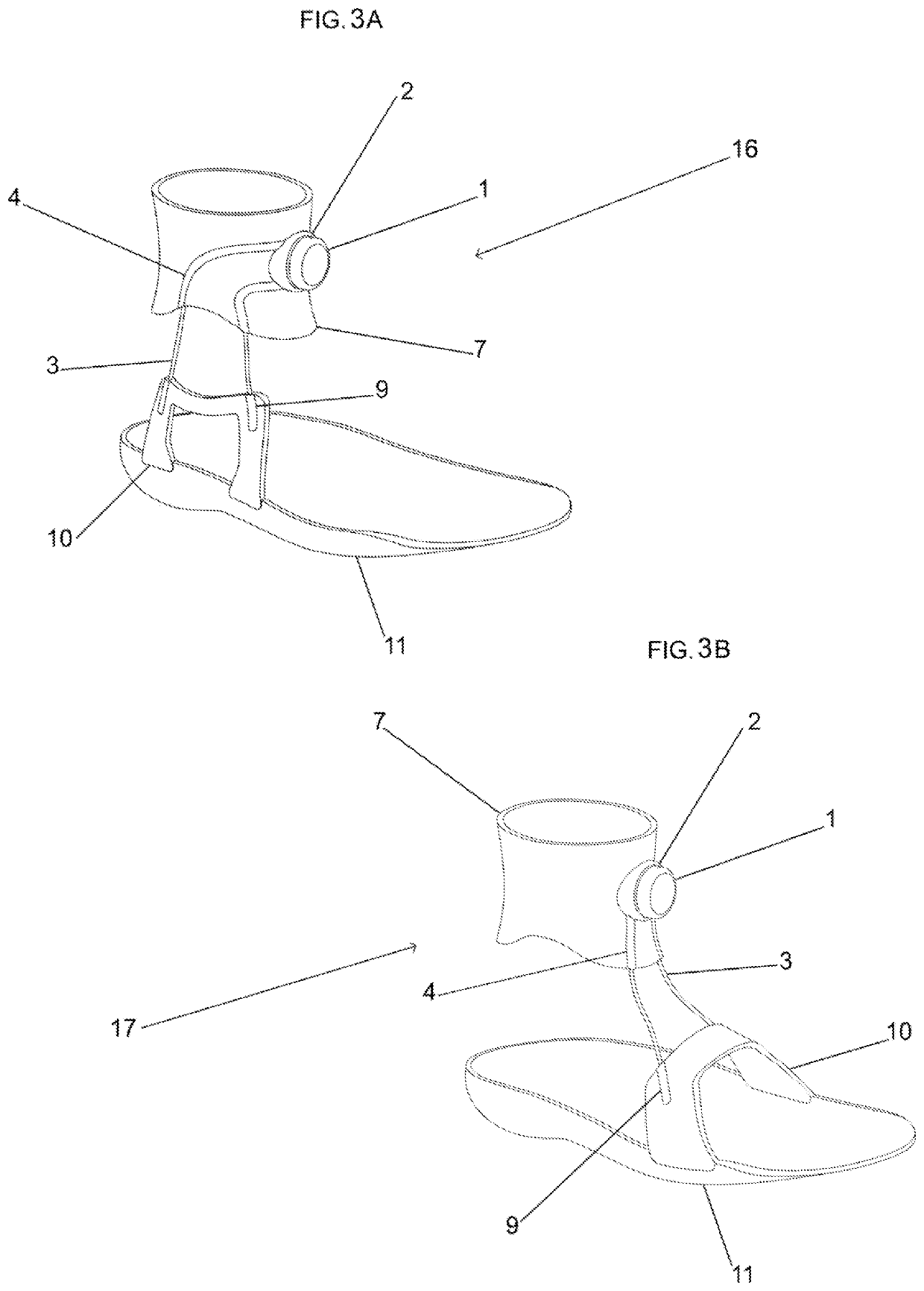
[0070]Embodiment three is comprised of a proximal cuff (7) and a sock (6) that incorporates a tensioning element (1,3,4,5). (See, FIG. 4A) The proximal cuff may be connected to the sock e.g. by sewing, hook and loop, hooks, buttons, or other fasteners. The proximal cuff and connected sock may also be one continuously manufactured unit or material. In this embodiment, the tensioning apparatus is comprised of an adjustment mechanism (1), one or more cable (3), one or more channel or pathway, optionally a tensioning element such as an elastic band, and optionally one or more cable guide. The adjustment mechanism (1) and adjustment mechanism insert (2) are the same as described in embodiment 1 (See, FIG. 2). Similarly, the adjustment mechanism may be connected to one or more cables as described in embodiment 1. In the example shown in FIG. 4A, rather than connecting to a tensioning element as described in embodi...


PUM


Abstract

A multi-axis rotation control ankle brace, wherein the direction and magnitude of force can be controlled around three axes of the ankle joint through an adjustable tensioning apparatus. The device may be applied to address conditions such as chronic ankle instability, foot drop, or osteoarthritis by providing such forces around the joint as an external-muscle tendon system to improve function, reduce pain, or restore mobility of the user. While more are contemplated herein, five preferred embodiments are specifically disclosed in the current application. Three preferred embodiments comprise a proximal portion and a distal portion, wherein the proximal portion is anchored above the ankle joint and houses, in aspects, the adjustment mechanism. The proximal portion is connected to the distal portion by tensioning or compressive elements, through which forces can be controlled by the user via the adjustment mechanism. In other preferred embodiments, the device is comprised of one continuous mesh, sock or sleeve through which tension can be controlled by the user. In other preferred embodiments, the device is personalized to the user through multiple aspects including user-enabled adjustment of forces around the joint. The device may be customized by 3D printing a device based on a digital scan, and therefore conforms to the user's ankle and foot.

Description

CROSS-REFERENCE TO RELATED APPLICATIONS[0001]The present application is a continuation-in-part of and relies on the disclosures of and claims priority to and the benefit of the filing dates of U.S. patent application Ser. Nos. 17 / 074,571 and 17 / 074,542 filed Oct. 19, 2020, U.S. patent application Ser. Nos. 17 / 211,590 and 17 / 211,635 filed Mar. 24, 2021, which rely on the disclosures of and claim priority to and the benefit of the filing date of U.S. patent application Ser. No. 15 / 585,968, filed May 3, 2017, which claims priority to and benefit from U.S. Provisional Patent Application No. 62 / 331,315 filed on May 3, 2016. This application also relates to and relies on the disclosures of and claims priority to and the benefit of the filing date of PCT / US2020 / 047904, filed Aug. 26, 2020. The disclosures of those applications are hereby incorporated by reference herein in their entirety.BACKGROUND OF THE INVENTIONField of the Invention[0002]The present invention disclosed herein relates t...

Claims


Application Information

Patent Timeline
IPC IPC(8): A61F5/01
CPCA61F5/0125A61F2005/0165A61F2005/0139A61F5/0113A61F5/0127A61F2005/0167A61H1/024A61H3/008A61H2201/1207A61H2201/1238A61H2201/1409A61H2201/1642A61H2201/5007A61H2201/5023A61H2201/5046A61H2201/5048A61H2201/5061A61H2201/5064A61H2201/5079A61H2201/5084A61H2201/5097A61H2230/045A61H2230/065A61H2230/085A61H2230/208A61H2230/505A61H2230/605A61H2230/625
Inventor JOHNSON, DAVID T.ECKERSLEY, EVANSCIRE, BENKITCHIN, CARTERMILLER, PHILIP
Owner ICARUS MEDICAL LLC
Why Eureka
Try Eureka