
Optical waveguide, manufacturing method of optical waveguide, and head-mounted display device

a manufacturing method and optical waveguide technology, applied in the field of optical waveguides, can solve the problems of affecting image quality, prone to large coupling microstructures, and spacing between image beams, and achieve the effects of increasing effective image beam density and uniformity, and improving the density and uniformity of sub image beams

Pending Publication Date: 2022-03-03
CORETRONIC
View PDF14 Cites 0 Cited by
  • Summary
  • Abstract
  • Description
  • Claims
  • Application Information

AI Technical Summary

Benefits of technology

The present patent describes a head-mounted display device that can provide high-quality images. The device uses a special optical design that separates the image beam into smaller sub-beams, which increases the density and uniformity of the image. This improves the image quality and makes it easier for the brain to process the information. Overall, the device provides a more immersive and realistic viewing experience for the user.

Problems solved by technology

If the spacing is larger, the spacing between the image beams with the same specific image information when they are guided out of the waveguide plate through the light—coupling-out microstructure is also prone to be larger.
This not only affects the image quality but is also an adversity to realizing a large viewing angle design in the optical engine of the head-mounted display.

Method used


Image

  • Optical waveguide, manufacturing method of optical waveguide, and head-mounted display device
  • Optical waveguide, manufacturing method of optical waveguide, and head-mounted display device
  • Optical waveguide, manufacturing method of optical waveguide, and head-mounted display device

Examples


Embodiment Construction

[0025]In the following detailed description of the preferred embodiments, reference is made to the accompanying drawings which form a part hereof, and in which are shown by way of illustration specific embodiments in which the disclosure may be practiced. In this regard, directional terminology, such as “top,”“bottom,”“front,”“back,” etc., is used with reference to the orientation of the Figure(s) being described. The components of the present disclosure can be positioned in a number of different orientations. As such, the directional terminology is used for purposes of illustration and is in no way limiting. On the other hand, the drawings are only schematic and the sizes of components may be exaggerated for clarity. It is to be understood that other embodiments may be utilized and structural changes may be made without departing from the scope of the present disclosure. Also, it is to be understood that the phraseology and terminology used herein are for the purpose of description...


PUM


Abstract

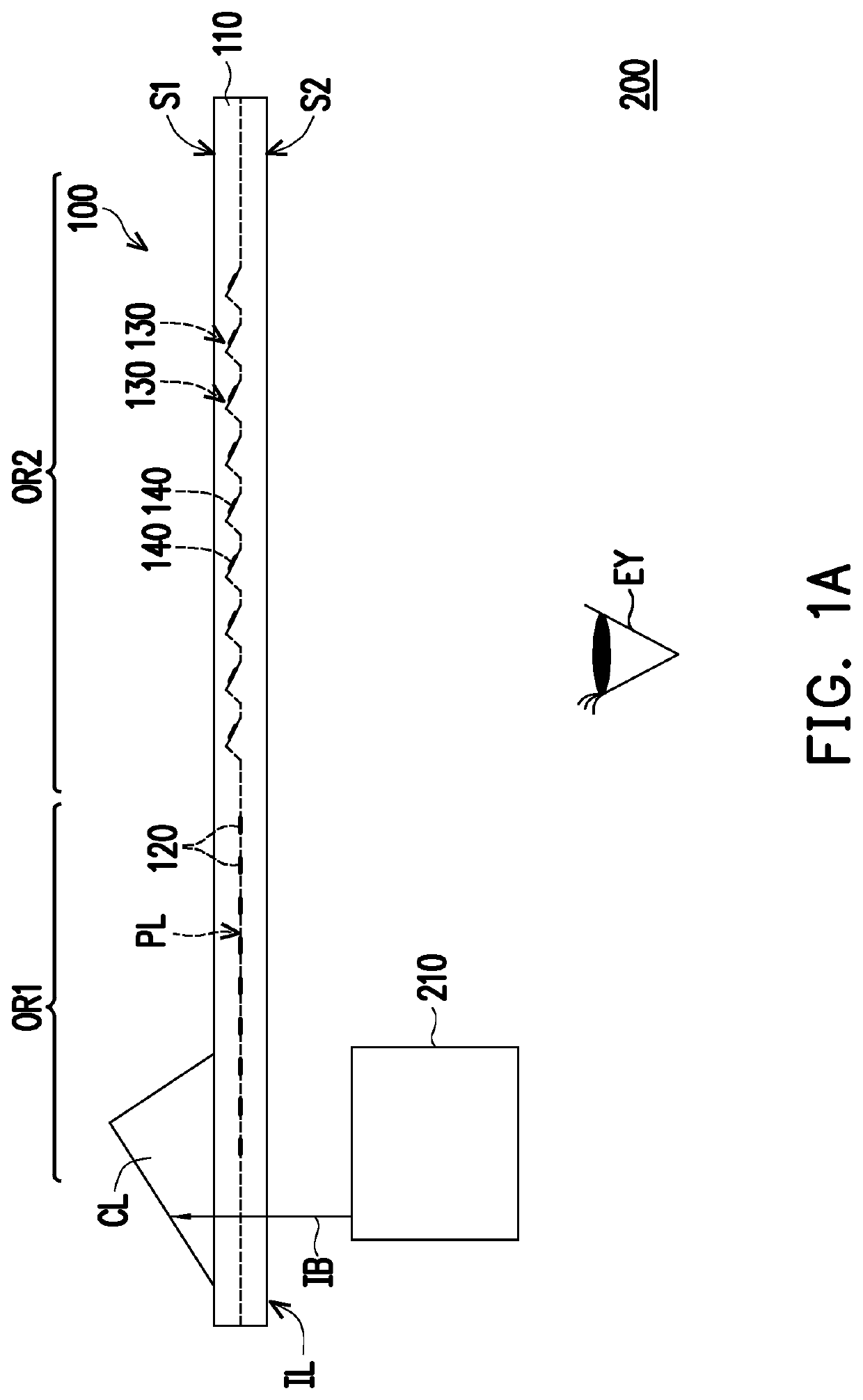
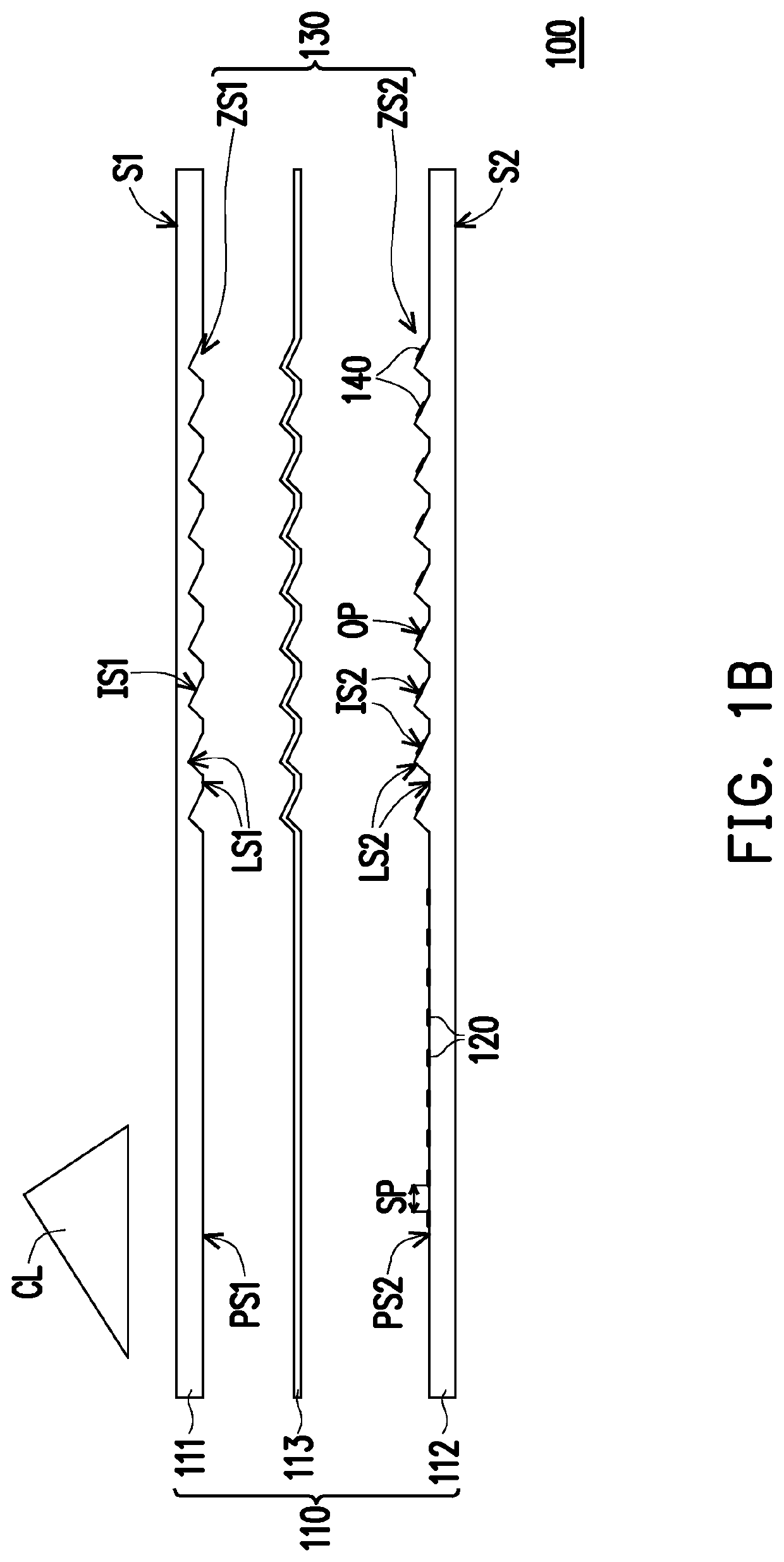
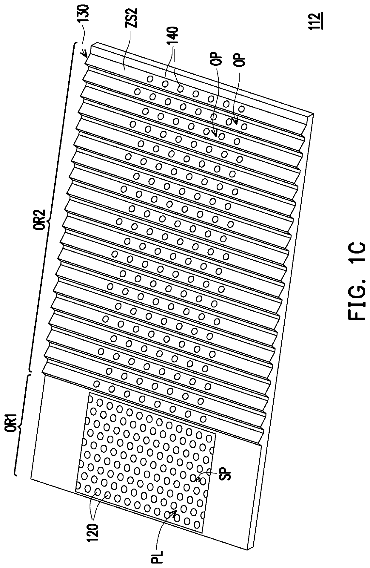
The disclosure provides an optical waveguide, a manufacturing method of an optical waveguide, and a head-mounted display device. The optical waveguide has a first optical region and a second optical region for transmitting an image beam. The optical waveguide includes a plate body, multiple first light-guiding optical elements, and multiple optical microstructures. The first light-guiding optical elements are disposed in parallel lines on a light-guiding plane inside the plate body. The light-guiding plane is located in the first optical region, and there is a spacing between the adjacent first light-guiding optical elements. The image beam transmitted to the light-guiding plane is separated into multiple sub image beams, and the transmission paths of the sub image beams are at least partially different. The optical coupling-out structure is disposed in the plate body and is located in the second optical region.

Description

CROSS-REFERENCE TO RELATED APPLICATION[0001]This application claims the priority benefit of China application serial no. 202010884312.9, filed on Aug. 28, 2020. The entirety of the above-mentioned patent application is hereby incorporated by reference herein and made a part of this specification.BACKGROUNDTechnical Field[0002]The disclosure relates to an optical structure, a manufacturing method of an optical structure, and an optical device, particularly to an optical waveguide, a manufacturing method of an optical waveguide, and a head-mounted display device.Description of Related Art[0003]With the advancement of display technique and people's demand for high technology, the technology of virtual reality and augmented reality have also gradually matured. And the head-mounted display (HMD) is the display adapted to implement above technology. The history of head-mounted displays can be traced back to the U.S. military in the 1970s, when an optical projection system is used to proje...

Claims


Application Information

Patent Timeline
IPC IPC(8): G02B27/01G02B6/34G02B6/12
CPCG02B27/0172G02B6/34G02B2006/12035G02B2006/12166G02B6/12004G02B6/00G02B27/10
Inventor CHIEN, HUNG-TA
Owner CORETRONIC
Learn More