
Heat-driven adsorption vacuum dehumidification system

a vacuum dehumidifier and vacuum technology, applied in the direction of heating types, lighting and heating apparatus, separation processes, etc., can solve the problems of short life cycle of abc and desiccant cooling system, low energy efficiency of desiccant cooling system, and inability to provide an integrated system in the foregoing references, so as to reduce carbon emission

Active Publication Date: 2022-03-03
CITY UNIVERSITY OF HONG KONG
View PDF1 Cites 0 Cited by
  • Summary
  • Abstract
  • Description
  • Claims
  • Application Information

AI Technical Summary

Benefits of technology

The patent describes a system that uses a two-bed adsorption-desorption section to extract moisture from air. The system includes an adsorption chamber and a desorption chamber. A cooling agent is used to keep the water vapor pressure in the adsorption chamber low, allowing moisture to be removed by the evaporator. A heating agent is used to keep the water vapor pressure in the desorption chamber high, allowing moisture to be expelled to the condenser. The system also includes a condenser that is cooled to a temperature that causes the water vapor to condense. This cooling can be done using a renewable energy source or waste source to significantly reduce carbon emissions. The technical effect of this system is to provide a more efficient and effective way to extract moisture from air, while also reducing carbon emissions.

Problems solved by technology

However, compared to AdC, life cycle of AbC as well as that of liquid desiccant cooling systems are short and costly in maintenance; solid desiccant cooling system is usually bulkier and lower in energy efficiency as it adds heat to air stream during dehumidification.
However, it also involves the use of refrigerant during the vapor compression process which is an environmental unfriendly process.
However, none of the foregoing references provide an integrated system that is absent in any environmental unfriendly refrigerant or coolant, or efficiently dehumidifies incoming air from the surroundings.
Both are not environmental-friendly as they create a lot of carbon dioxide emission and noise.
Among those VD systems equipped with electric vacuum pumps, their COP are not much better than that of AdC in a small- to medium-sized application due to their lower electrical efficiencies in such circumstance.

Method used


Image

  • Heat-driven adsorption vacuum dehumidification system
  • Heat-driven adsorption vacuum dehumidification system
  • Heat-driven adsorption vacuum dehumidification system

Examples


example 1

Comparison of Performances Between AdC and the Present System in Terms of Different Combination / Sequence of Operating Conditions

[0065]Table 1 shows the effect of different combination / sequence of operational conditions on CAP and COP of AdC and the present system.

TABLE 1AdCPresent InventionCycle SequenceCAP / COPCAP / COPPIICAP / PIICOPAdDe0.593 / 0.2051.016 / 0.3170.713 / 0.546PHC + AdDe0.596 / 0.2141.009 / 0.3260.693 / 0.523AdDe + HMR0.612 / 0.2691.105 / 0.4250.806 / 0.580PHC + AdDe + HMR0.615 / 0.2791.077 / 0.4310.751 / 0.545

[0066]From Table 1, the overall CAP and COP of the present invention are better than those of AdC (at least about 69.3% and 52.3% enhancement in CAP and COP, respectively, over AdC). COP of the present invention is also comparable to that of conventional VD using electrical vacuum dehumidification such as that by Bui et al. (2017) with the inclusion of HMR mode. The present invention is also coil-free in the evaporation step and cooling step as compared to conventional chilled water-based...

example 2

Variations of COP and CAP Under Different Operating Conditions

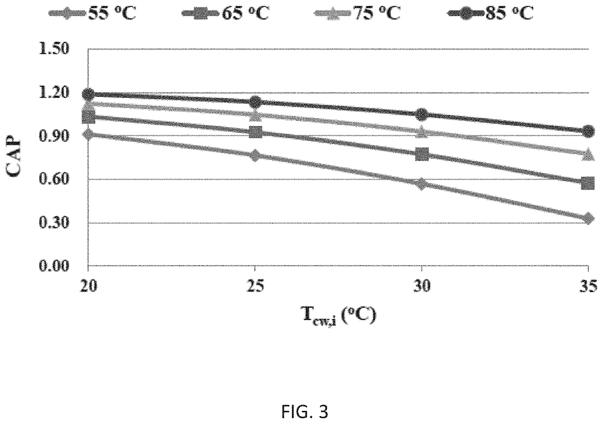
[0068]FIGS. 3 and 4 show the variations of CAP and COP against different temperatures of the cooling water / hot water supplied to the adsorption / desorption chamber of the present invention. In FIG. 3, CAP of the present system was decreased with an increase in cooling water temperature or with a decrease in hot water temperature, which is similar to the trend in conventional AdC. However, it is observed that variation of COP of the present system at higher hot water temperature, e.g., at 85° C., resulted in an increasing trend against an increasing cooling water temperature, which is different from a comparative test result of AdC. The increasing trend was not obvious when the cooling water temperature was equal to or below 30° C. However, when the cooling water temperature was over 30° C., it is observed that the higher the hot water temperature, the more likely the COP is increased. This phenomenon was not observed in ho...

example 3

Variation of PII Under Different Operating Conditions

[0071]FIGS. 6 and 7 show the changes of PIICAP and PIICOP cop against different temperatures of the cooling water / hot water supplied to the adsorption / desorption chamber of the present invention. The present invention out-performs the AdC more substantially when the cooling water temperature increases and / or the hot water temperature decreases. This characteristic is particularly beneficial when applied to a solar cooling system as the system performance does not reduce much when the solar energy is not sufficient.


PUM

PropertyMeasurementUnit
temperatureaaaaaaaaaa

Abstract

The present invention provides a heat-driven adsorption vacuum dehumidification system including a vapor adsorption apparatus having a water permeable hydrophilic membrane separating the apparatus into at least a feed section and a low-pressure or vacuum section (evaporator), and providing a water vapor pressure difference to extract moisture from the air flowing through the apparatus into the evaporator, followed by adsorption in an adsorption chamber, and subsequently desorbed when acted as a desorption chamber to form water vapor which is condensed in a condenser. Adsorption and desorption chambers inter-change periodically to form a complete system cycle. Heating of chamber / compartment can be from waste heat or a renewable source in the absence of any electricity supplied externally. Related method for using a heat-driven adsorption vacuum dehumidification system to remove moisture from the air is also provided. The present invention is superior to the adsorption chiller over a wide range of operating conditions.

Description

CROSS-REFERENCE WITH RELATED APPLICATIONS[0001]The present application claims priority from the U.S. Provisional Patent Application No. 63 / 071,514 filed Aug. 28, 2020, and the disclosure of which is incorporated herein by reference in its entirety.FIELD OF THE INVENTION[0002]The present invention relates to a dehumidifier system. In particular, the present invention relates to a heat-driven vacuum dehumidifier system incorporating a vapor adsorption apparatus to enable dehumidification in the absence of electricity-driven vacuum pump but rather driven by heat from an external source to create a water vapor pressure difference between an interior space and the process air stream.BACKGROUND[0003]Air-conditioning systems are used to be a major electricity consumer and carbon footprint in a modern city. With the demand for a better air ventilation in indoor environment, especially under the Covid-19 pandemic, more efforts have been made to attempt to meet the increasing energy demand by...

Claims


Application Information

Patent Timeline
Patent Type & Authority Applications(United States)
IPC IPC(8): B01D53/26B01D53/04F24F3/14
CPCB01D53/268B01D53/261B01D53/265B01D53/0438F24F2003/144B01D2253/106B01D2257/80B01D2259/40088B01D2259/402F24F3/1411F24F2003/1435F24F2003/1458
Inventor FONG, KWONG FAILEE, CHUN KWONG
Owner CITY UNIVERSITY OF HONG KONG
Learn More