
P-doped surface coatings and process of preparation thereof

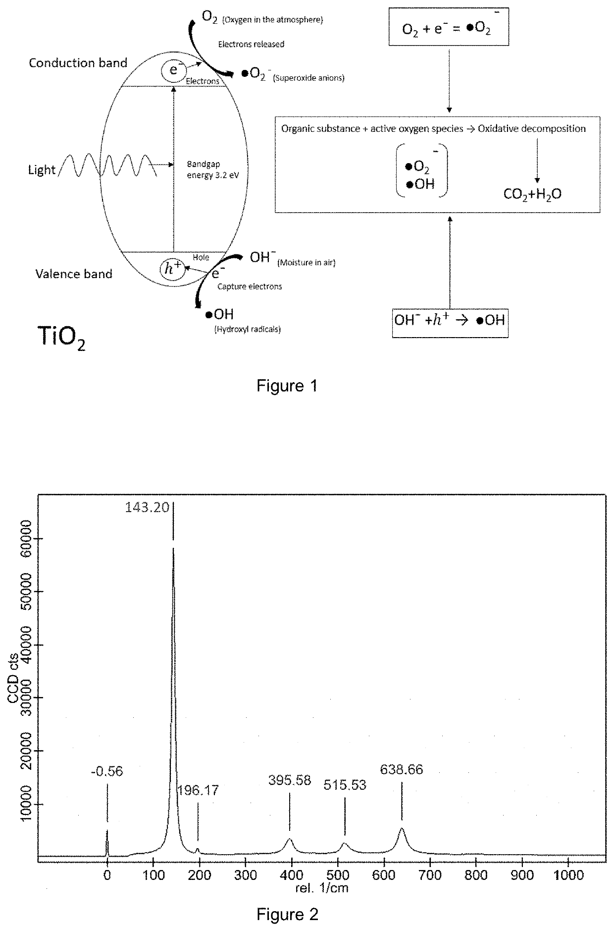
a technology of surface coating and pdoping, which is applied in the direction of biocides, coatings, liquid/solution decomposition chemical coatings, etc., can solve the problems of increasing ‘carbon foot print and higher cost, and achieves reduced bandgap energy, less acidic, and improved doping efficiency

Pending Publication Date: 2022-01-27
KASTUS TECH DAC
View PDF0 Cites 0 Cited by
  • Summary
  • Abstract
  • Description
  • Claims
  • Application Information

AI Technical Summary

Benefits of technology

This patent describes a process for creating a coated substrate with an antimicrobial coating that can be used for a variety of applications such as glass, ceramics, plastic, and cement. The process involves using a phosphoric acid solution that contains a stable precursor that is non-volatile and non-oxidizing. This makes the handling and storage of the solution easier, and no additional equipment is needed on the production line. The composition can be applied in liquid form to the substrate using various methods such as spraying, dipping, roller, brush, or electrostatic methods. The resulting coating has effective antimicrobial properties and can be shipped and stored in small amounts for several months without losing its effectiveness. This process is cost-effective and suitable for a wide range of applications.

Problems solved by technology

However, this inclusion of an organic solvent would increase the ‘carbon foot print’ and the cost would be higher than in the embodiments in which the aqueous solution relies entirely on water as the solvent.

Method used


Image

  • P-doped surface coatings and process of preparation thereof
  • P-doped surface coatings and process of preparation thereof
  • P-doped surface coatings and process of preparation thereof

Examples


example 2

[0100]KCS111:[0101]1. 10 mL TTIP was placed in a polypropylene beaker.[0102]2. 19.2 mL glacial acetic acid was added while stirring.[0103]3. 0.14 mL 86% orthophosphoric acid (aqueous) was added while stirring. A small quantity of white precipitate began to form.[0104]4. 120 mL deionised water was added while stirring and the mixture stirred for a further 40 minutes. A sol with a translucent milky white appearance was formed and the precipitate previously formed re-dispersed, which was then bottled.

example 3

[0105]KCS112:[0106]1. 10 mL TTIP was placed in a polypropylene beaker.[0107]2. 19.2 mL glacial acetic acid was added while stirring.[0108]3. 0.5 mL 86% orthophosphoric acid (aqueous) was added while stirring. A larger quantity of white precipitate began to form than in the case of KCS111.[0109]4. 120 mL deionised water was added while stirring and the mixture stirred for a further 40 minutes. A sol with a translucent milky white appearance was formed, that was denser in colour than KCS111, which was then bottled.

example 4

[0110]Example 4 describes an alternative embodiment, wherein the order of addition of the reagents is as follows:[0111]a) TTIP[0112]b) Glacial acetic acid[0113]c) De-ionised water[0114]d) Orthophosphoric acid (aqueous)[0115]A dispersing agent may be added following the addition of orthophosphoric acid.

[0116]KCS117:[0117]Orthophosphoric acid can be added after the addition of the deionised water to the glacial acetic acid / TTIP mixture.[0118]1. 10 mL TTIP was placed in a polypropylene beaker.[0119]2. 19.2 mL glacial acetic acid was added while stirring.[0120]3. 120 mL deionised water was added while stirring and the mixture stirred for 20 minutes. A sol with a translucent milky white appearance was formed.[0121]4. 0.14 mL 86% orthophosphoric acid (aqueous) was added while stirring. A small quantity of white precipitate began to form. The sol was stirred for a further 40 minutes and this precipitate re-dispersed.


PUM

PropertyMeasurementUnit
temperatureaaaaaaaaaa
temperaturesaaaaaaaaaa

Abstract

A process for the preparation of an antimicrobial P-doped coating solution is described. The process for the preparation of the antimicrobial coating solution uses non-volatile and non-oxidising phosphoric acid. The antimicrobial coatings are active in both the UV and visible light spectrum.

Description

FIELD[0001]The present application relates to anti-microbial coatings for surfaces; and more particularly to coatings doped by phosphorus which are referred to as “P-doped coatings” and which are active in both the UV and visible light spectrum.BACKGROUND OF THE INVENTION[0002]TiO2 has been extensively used in different photocatalytic applications including antimicrobial coatings. The main photoactive polymorphs of TiO2 are anatase and brookite, with anatase being the most efficient. The photocatalytic effect initiates by absorbing light with an energy equal to or greater than the bandgap of TiO2. Consequently, the electrons in the valence are excited to the conduction band, while positive holes form in the valence band. These photoexcited electrons and photogenerated positive holes are responsible for photocatalytic reactions.[0003]To make photocatalysts responsive to visible light, it is necessary to narrow the band gap energy between the valence band and the conduction band or to...

Claims


Application Information

Patent Timeline
Patent Type & Authority Applications(United States)
IPC IPC(8): C09D7/80C09D5/14C09D7/63C09D7/61
CPCC09D7/80C09D7/61C09D7/63C09D5/14C09D1/00C23C18/1254C23C18/1216C23C18/1241
Inventor KENNEDY, JAMESLEYLAND, NIGEL
Owner KASTUS TECH DAC
Learn More