Bone plate system comprising a fastening element having a hard surface

a technology of fastening elements and bone plates, which is applied in the direction of bone plates, fasteners, osteosynthesis devices, etc., can solve the problems of increasing the manufacturing cost of plates, affecting the stability of the system, so as to achieve the effect of simple design, low plate manufacturing cost and efficient and inexpensiv

Active Publication Date: 2021-12-09
41MEDICAL AG
View PDF0 Cites 2 Cited by
  • Summary
  • Abstract
  • Description
  • Claims
  • Application Information

AI Technical Summary

Benefits of technology

[0007]The proposed solution has the advantage that it offers very efficient and inexpensive way of locking fastening elements to a bone plate of the system. Thanks to the simple design of the bone plate and its holes, the manufacturing costs of the plate can be kept low and various manufacturing processes may be used to produce the plates. Further advantages are for example: very high surface hardness of the fastening element, low risk of producing metal chips when inserting screws into the holes (thanks to the hardness difference), easy to design the locking mechanism for different dimensions, the fastening elements perform substantially the same manner irrespective of the insertion direction and / or position, easy removal and re-insertion of the fastening elements, very high angle stability and reproducibility for each angle even if the fastening elements are removed and re-inserted optionally at a different angle. Furthermore, by choosing the materials appropriately, a high corrosion resistance can be achieved as well as high surface quality.

Problems solved by technology

Furthermore, the plate manufacturing costs also directly depend on the plate hole design.
In other words, a complex hole design typically increases the manufacturing costs of the plate.
Currently known locking mechanisms typically have some limitations, such as high complexity, limited angle stability, high variation of angle stability, voluminous design, bad usability, bad reproducibility and / or high screw insertion torque.
Biocompatibility is also an issue when designing bone plates.

Method used


Image

  • Bone plate system comprising a fastening element having a hard surface
  • Bone plate system comprising a fastening element having a hard surface
  • Bone plate system comprising a fastening element having a hard surface

Examples


Embodiment Construction

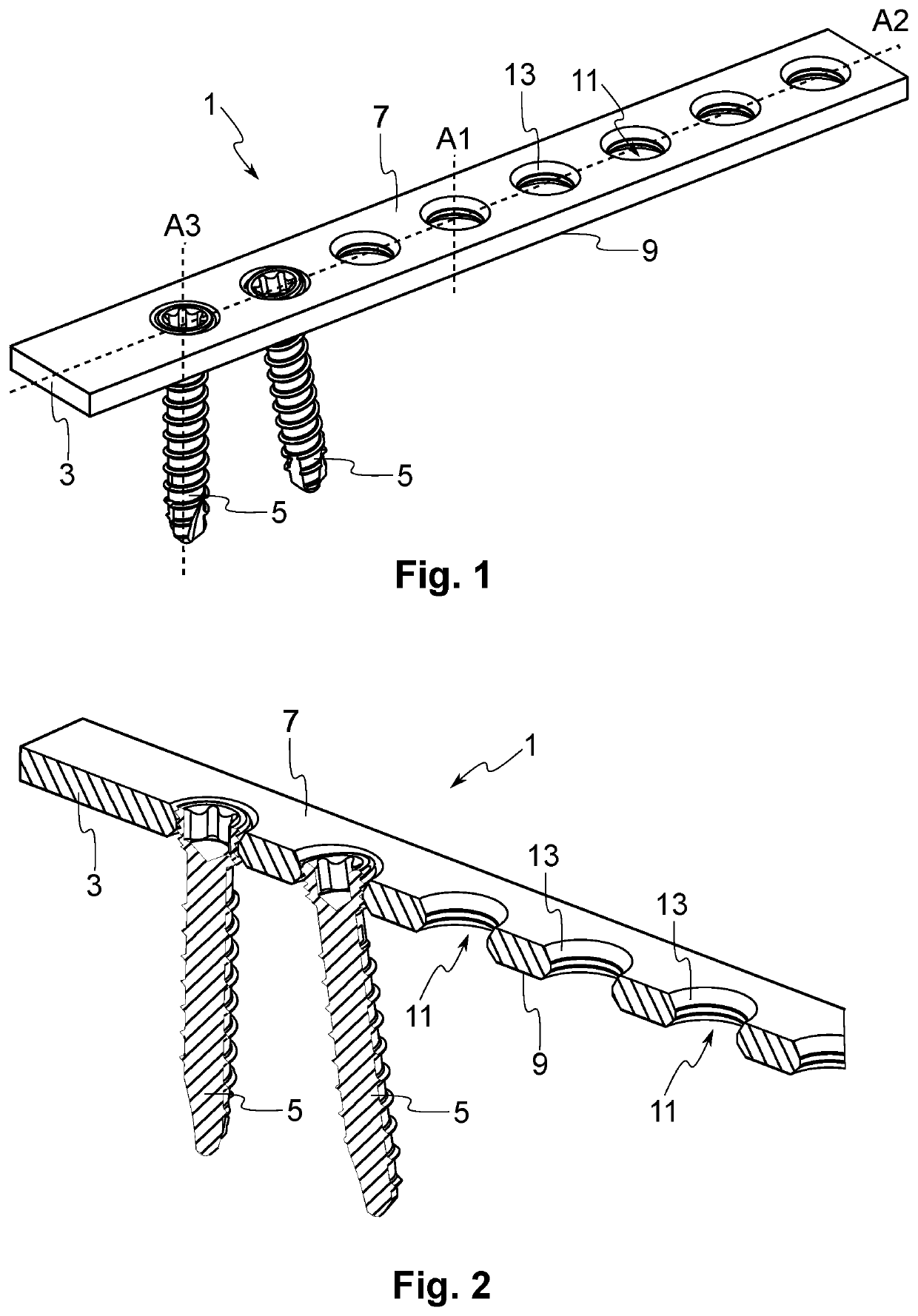
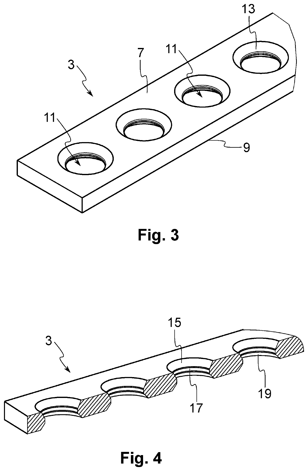
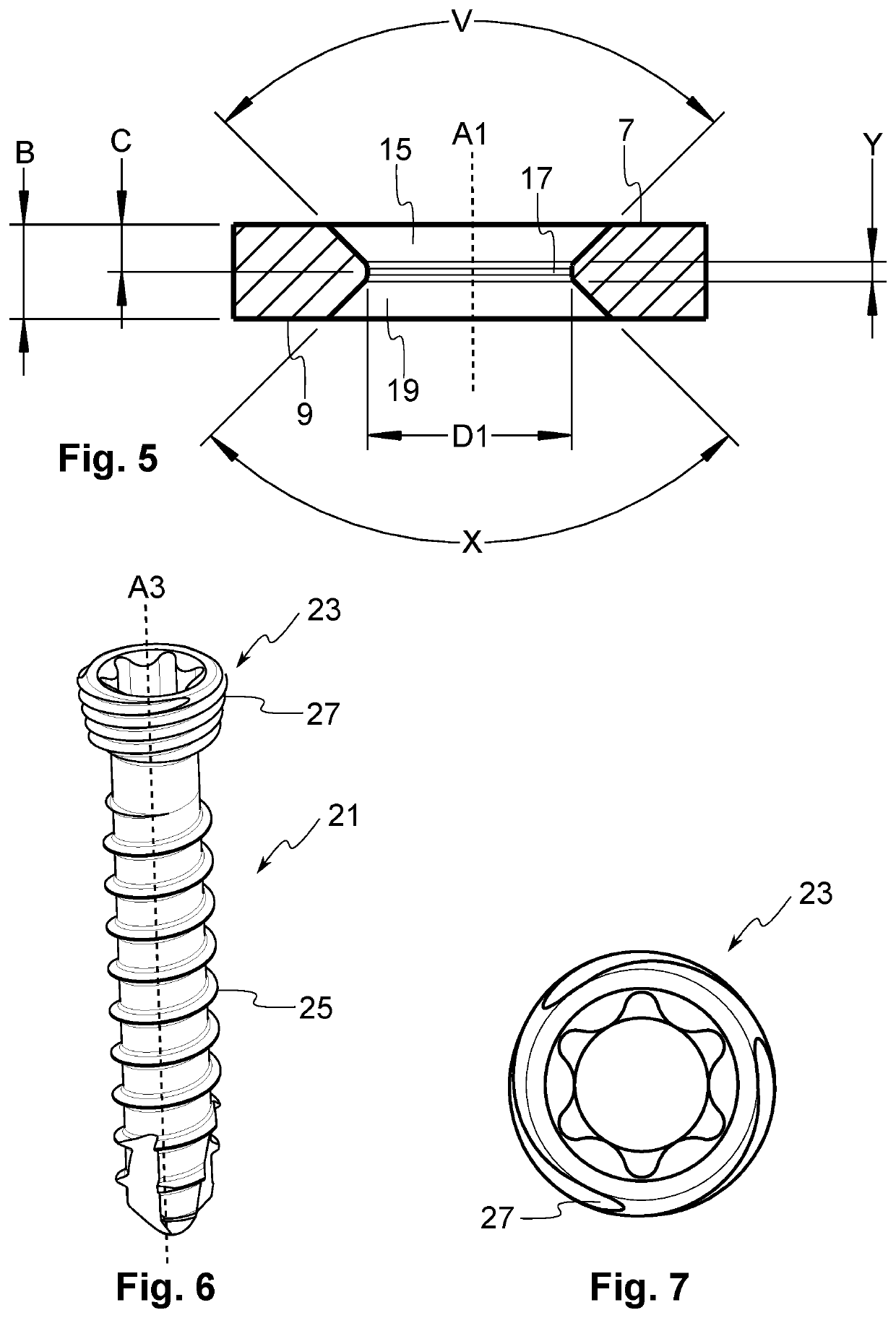
[0021]An example embodiment of the present invention will now be described in detail with reference to the attached drawings. The embodiment is described in the context of a variable-angle bone plate system or assembly for bridging at least two bone segments. The proposed bone system may be used for instance for trauma, spine and / or craniomaxillofacial (CMF) procedures. However, the teachings of the invention are not limited to this environment or application. Identical or corresponding functional and structural elements which appear in the different drawings are assigned the same reference numerals. As utilised herein, “and / or” means any one or more of the items in the list joined by “and / or”. As an example, “x and / or y” means any element of the three-element set {(x), (y), (x, y)}. In other words, “x and / or y” means “one or both of x and y.” As another example, “x, y, and / or z” means any element of the seven-element set {(x), (y), (z), (x, y), (x, z), (y, z), (x, y, z)}. In other ...


PUM


Abstract

The invention concerns a bone plate system comprising: a bone fastening element comprising a shaft with a first thread, the fastening element further comprising a head with a second thread on its outer surface, the outer surface having a first hardness; and a bone plate having a second hardness which is smaller than the first hardness, the bone plate comprising a through hole for receiving the bone fastening element. The head is oxygen diffusion hardened.

Description

TECHNICAL FIELD[0001]The present invention relates to a bone plate system comprising a bone plate and a fastening element, such as a screw. At least a portion of the fastening element is harder than the bone plate.BACKGROUND OF THE INVENTION[0002]Bone tissue, unlike most of the human body's tissues, has the remarkable ability to regenerate itself. If a fractured bone can be held together for a given period of time, it can regenerate the tissue and regain most of its original strength. For various fractures, bone plates are surgically implanted to hold the bone in place. A bone plate is typically a relatively thin metal implant used to immobilise bone segments. The plate comprises holes or perforations for receiving fastening elements, such as screws, so that the plate is affixed with the fastening elements to properly align the bone and aid in the healing process.[0003]The interface between the screw and the bone plate forms a screw locking mechanism for locking screws and is an imp...

Claims


Application Information

Patent Timeline
Patent Type & Authority Applications(United States)
IPC IPC(8): A61B17/80A61B17/86
CPCA61B17/8057A61B17/866A61B17/8047A61B17/8052A61B17/8061
Inventor FRIGG, ROBERTZURSCHMIEDE, SILASBURKI, PATRICKFLURI, DANIEL
Owner 41MEDICAL AG
Why Eureka
Try Eureka