Electrochemical hydrogen pump
a hydrogen pump and electrochemical technology, applied in the field can solve the problems of large-scale facilities and land, reduced efficiency of electrochemical hydrogen pumps, and increased voltage required to carry current, so as to reduce efficiency and increase contact resistance
- Summary
- Abstract
- Description
- Claims
- Application Information
AI Technical Summary
Benefits of technology
Problems solved by technology
Method used
Image
Examples
embodiment 1
[0061]Electrochemical hydrogen pump 24 according to Embodiment 1 of the present disclosure is described below with reference to FIG. 3A and FIG. 3B. FIG. 3A is a schematic cross-sectional view including the cathode inlet / outlet of electrochemical hydrogen pump 24 of the present embodiment. FIG. 3B is a schematic sectional view including the anode inlet / outlet of electrochemical hydrogen pump 24 of the present embodiment.
General Configuration
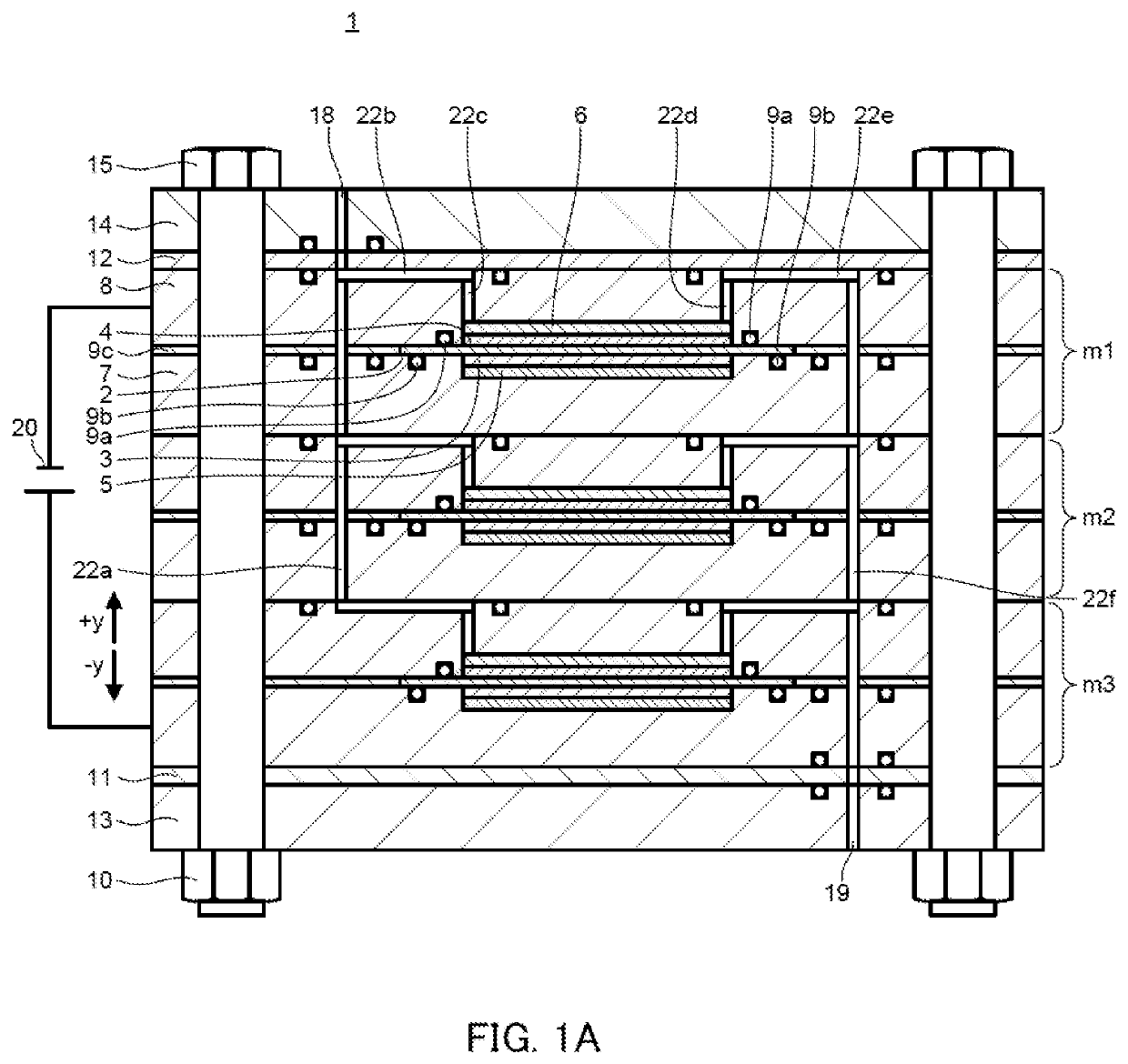
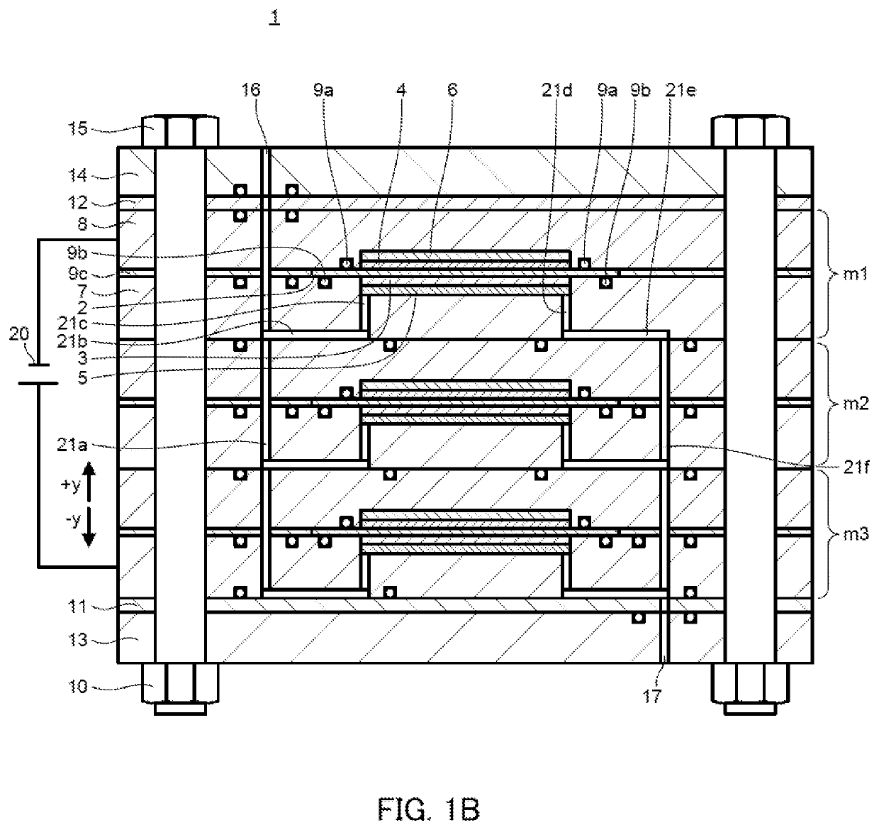
[0062]In electrochemical hydrogen pump 24 illustrated in FIG. 3A and FIG. 3B, three single battery cells m1, m2 and m3 are stacked as in power generation stack 1 illustrated in FIG. 1A and FIG. 1B.
[0063]In electrochemical hydrogen pump 24, anode end plate 13, anode insulation plate 11, A-end separator 7a, single battery cell m3, single battery cell m2, single battery cell m1, C-end separator 8a, C-pressure plate 8b, cathode insulation plate 12, and cathode end plate 14 are stacked in this order from the bottom side, and they are fastened with bol...
embodiment 2
[0132]Electrochemical hydrogen pump 25 according to Embodiment 2 of the present disclosure is described below with reference to FIG. 4. FIG. 4 is a schematic cross-sectional view including a cathode inlet / outlet of electrochemical hydrogen pump 25 of the present embodiment.
General Configuration
[0133]In electrochemical hydrogen pump 25, anode end plate 13, anode insulation plate 11, A-end separator 7a, single battery cell m3, single battery cell m2, single battery cell m1, C-end separator 8a, cathode insulation plate 12, and cathode end plate 14 are stacked in this order from the bottom side, and they are fastened with bolt 15 and nut 10 in the state where they are in intimate contact with each other.
[0134]Anode pressure space 27 is formed in anode insulation plate 11 (an example of the anode side member). In addition, cathode pressure space 28 is formed in cathode insulation plate 12 (an example of the cathode side member).
[0135]Anode pressure space 27 is communicated with cathode i...
embodiment 3
[0147]Electrochemical hydrogen pump 26 according to Embodiment 3 of the present disclosure is described below with reference to FIG. 5. FIG. 5 is a schematic cross-sectional view of a cathode inlet / outlet of electrochemical hydrogen pump 26 of the present embodiment.
General Configuration
[0148]In electrochemical hydrogen pump 26 illustrated in FIG. 5, three single battery cells m1a, m2a and m3a are stacked.
[0149]Configurations of single battery cells m1a, m2a and m3a are described below.
[0150]Each of single battery cells m1a, m2a and m3a includes anode separator 7, anode diffusion layer 5, anode electrode layer 3, electrolyte membrane 2, seal 9c, cathode electrode layer 4, and cathode diffusion layer 6. These components are the same as those of electrochemical hydrogen pump 25 of Embodiment 1.
[0151]In the present embodiment, each of single battery cells m1a, m2a and m3a includes first cathode separator 8c and second cathode separator 8d in place of cathode separator 8 described in Em...
PUM
 Abstract
Description
Claims
Application Information
 - R&D Engineer
- R&D Manager
- IP Professional
- Industry Leading Data Capabilities
- Powerful AI technology
- Patent DNA Extraction
Browse by: Latest US Patents, China's latest patents, Technical Efficacy Thesaurus, Application Domain, Technology Topic, Popular Technical Reports.
© 2024 PatSnap. All rights reserved.Legal|Privacy policy|Modern Slavery Act Transparency Statement|Sitemap|About US| Contact US: help@patsnap.com


