Device for Measuring the Thickness of Coatings
- Summary
- Abstract
- Description
- Claims
- Application Information
AI Technical Summary
Benefits of technology
Problems solved by technology
Method used
Image

Examples
Embodiment Construction
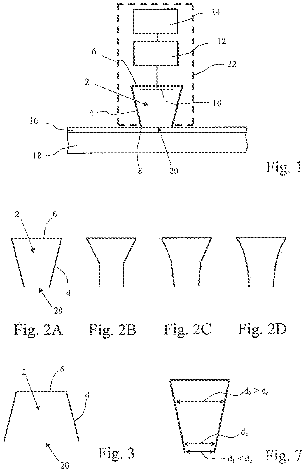
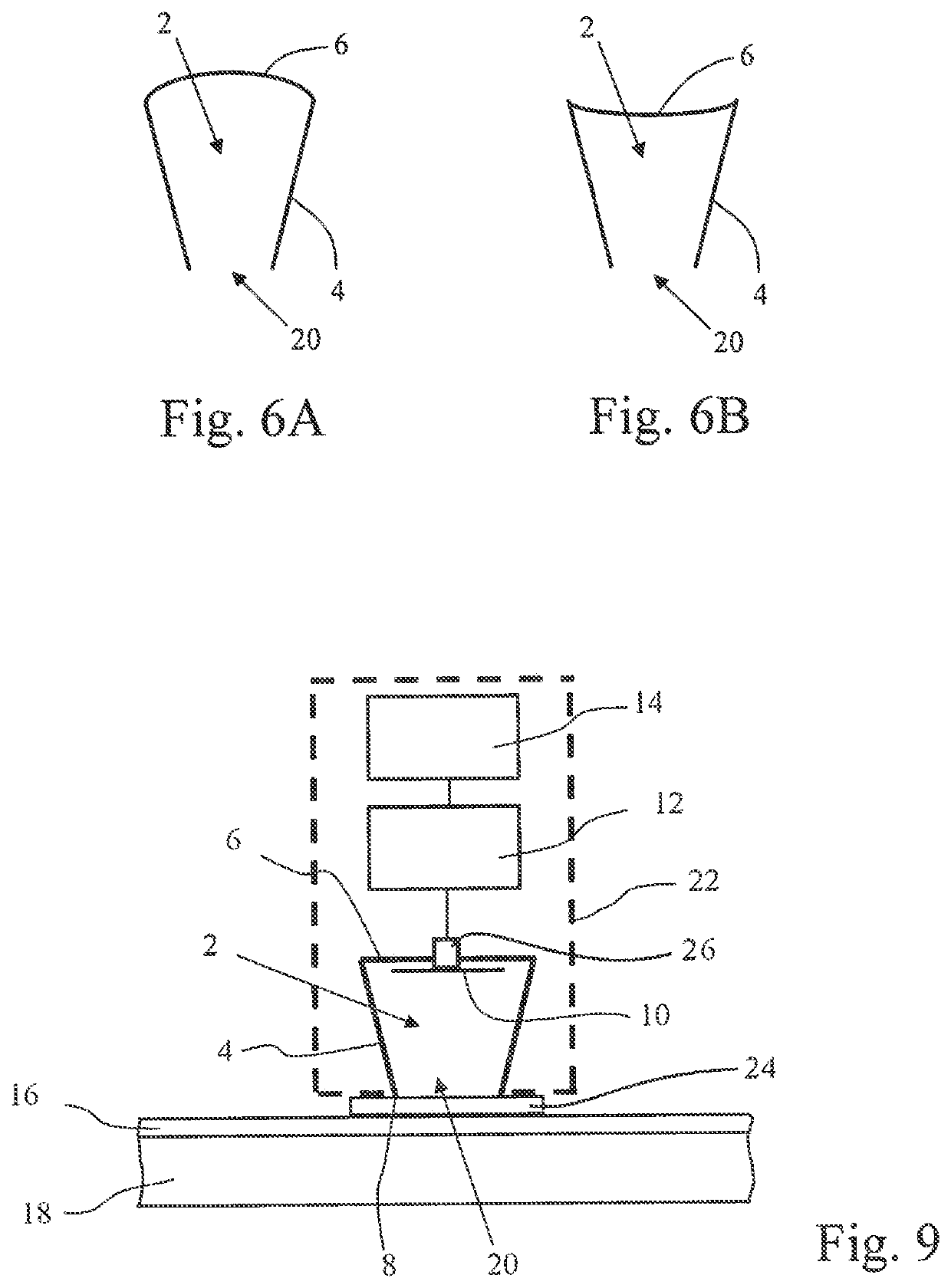
[0037]FIG. 1 shows a diagram of an embodiment of the measuring device according to the invention in section. An end plate 6 (or end wall) and a rotationally symmetrical wall 4 form a resonance cavity 2 for electromagnetic (wave) fields which is open at one end 8, wherein the diameter of the rotationally symmetrical wall 6 is not constant. The rotationally symmetrical wall 4 and the end plate 6 are made of a conductive material (metal). The resonance cavity 2 is adapted to be positioned with the open end 8 which lies opposite the end plate 6 on a dielectric layer 16 which is located on a substrate 18 made of a conductive material and the thickness whereof is to be measured. Furthermore, the device comprises an antenna 10 which is adapted to excite an electromagnetic field in the resonance cavity 2.
[0038]The end plate 6 and the rotationally symmetrical wall 4 are conductive and therefore form together with the substrate 18 a substantially closed cavity (“substantially” since the diele...
PUM
 Abstract
Description
Claims
Application Information
 - R&D
- Intellectual Property
- Life Sciences
- Materials
- Tech Scout
- Unparalleled Data Quality
- Higher Quality Content
- 60% Fewer Hallucinations
Browse by: Latest US Patents, China's latest patents, Technical Efficacy Thesaurus, Application Domain, Technology Topic, Popular Technical Reports.
© 2025 PatSnap. All rights reserved.Legal|Privacy policy|Modern Slavery Act Transparency Statement|Sitemap|About US| Contact US: help@patsnap.com