System and method for cleaning a laser cut substrate
a laser cut paper and cleaning technology, applied in the direction of cleaning using liquids, manufacturing tools, chemistry apparatus and processes, etc., can solve the problems of affecting the aesthetic affecting the cleaning effect, and affecting the appearance of the cut paper
- Summary
- Abstract
- Description
- Claims
- Application Information
AI Technical Summary
Benefits of technology
Problems solved by technology
Method used
Image

Examples
first embodiment
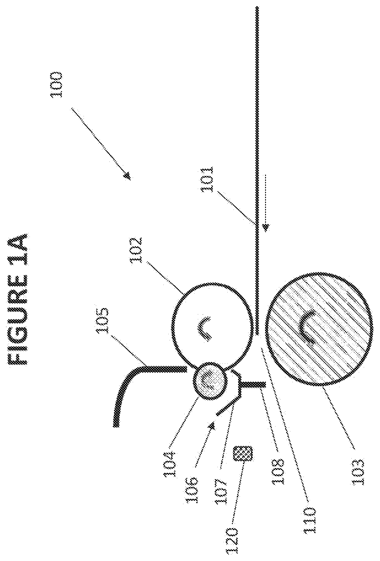
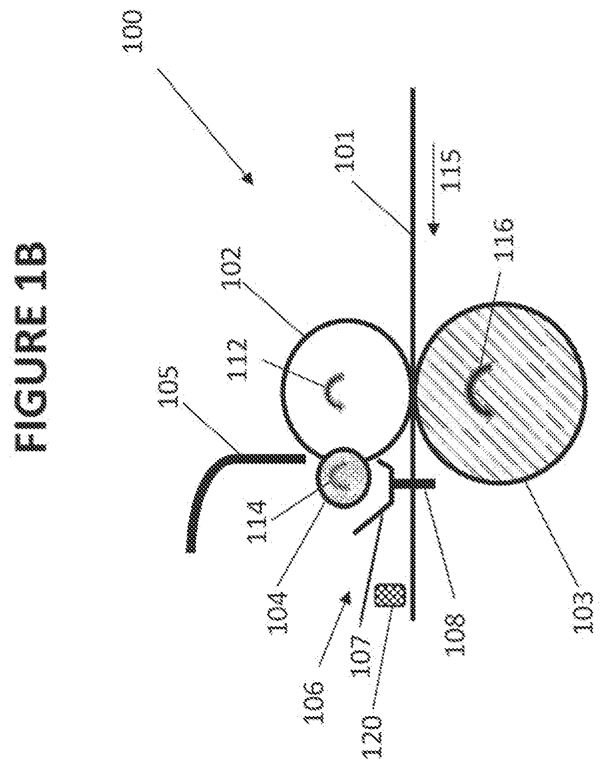
[0072]Reference is now made to FIGS. 1A and 1B, which are schematic sectional illustrations of an inventive system 100 for cleaning HAZ from a broad surface of a paper substrate 101 according to an embodiment of the teachings herein.
[0073]As seen in FIGS. 1A and 1B, system 100 includes a cleaning element, which in the embodiment of FIGS. 1A and 1B is a cleaning roller 102, formed entirely of a resilient compressible material, preferably foam.
[0074]In some embodiments, the foam is selected from the group consisting of open rubber foam, reticulated foam, and felted foam. In some embodiments, the foam is formed of a material selected from the group of nitrile rubber, EPDM rubber, natural rubber, PVC, polyester, polyether, and polyurethane.
[0075]In some embodiments, the foam has a density in the range of 0.1 g / cm3 to 0.4 g / cm3, or 0.15 g / cm3 to 0.30 g / cm3.
[0076]In some embodiments, the foam has a 25% compression pressure in the range of 2 psi to 50 psi, 3 psi to 40 psi, or 5 psi to 30 p...
second embodiment
[0122]Reference is now made to FIG. 2A, which is a schematic sectional illustration of an inventive system 200 for cleaning HAZ from a paper substrate 101 according to another embodiment of the teachings herein. System 200 is illustrated in FIG. 2 in the resting mode, similar to the illustration in FIG. 1A, and has an operative mode as described hereinabove with respect to FIG. 1B.
[0123]System 200 is similar to system 100 of FIGS. 1A and 1B, with like numbers indicating like elements. System 200 differs from system 100 in that cleaning roller 102 of system 200 is not formed entirely of a resilient compressible material such as foam, but rather is formed of a foam layer 201, or layer of another resilient compressible material, surrounding a rigid core 202. As such, in operation of system 200, liquid provided from pipe 105 is absorbed only in foam layer 201, and only foam layer 201 is squeezed by squeezing roller 104.
[0124]In some embodiments, rigid core 202 is formed of at least one ...
third embodiment
[0149]Reference is now made to FIG. 6, which is a schematic sectional illustration of an inventive system 600 for cleaning HAZ from a paper substrate 601 according to an embodiment of the teachings herein.
[0150]As seen in FIG. 6, system 600 includes a cleaning element, here illustrated as a cleaning roller 602, formed entirely of foam, substantially as described hereinabove with respect to cleaning roller 102 of FIGS. 1A and 1B.
[0151]System 600 also includes a counter and / or support element, here illustrated as a counter roller 603, which forms a counter to cleaning roller 602. The paper substrate 601 is adapted to be driven between cleaning roller 602 and counter roller 603, such that cleaning roller 602 is disposed vertically beneath paper substrate 601 and counter roller 603.
[0152]System 600 further includes a liquid source, which in the embodiment of FIG. 6 is a pipe 605, in communication with a reservoir (not explicitly shown), similar to pipe 105 of FIGS. 1A and 1B. Pipe 605 i...
PUM
| Property | Measurement | Unit |
|---|---|---|
| Fraction | aaaaa | aaaaa |
| Fraction | aaaaa | aaaaa |
| Fraction | aaaaa | aaaaa |
Abstract
Description
Claims
Application Information
 - R&D
- Intellectual Property
- Life Sciences
- Materials
- Tech Scout
- Unparalleled Data Quality
- Higher Quality Content
- 60% Fewer Hallucinations
Browse by: Latest US Patents, China's latest patents, Technical Efficacy Thesaurus, Application Domain, Technology Topic, Popular Technical Reports.
© 2025 PatSnap. All rights reserved.Legal|Privacy policy|Modern Slavery Act Transparency Statement|Sitemap|About US| Contact US: help@patsnap.com