Cell Culture Apparatus

a cell culture and apparatus technology, applied in the field of cell culture apparatus, can solve the problems of large size of the wound band in the radial direction, unsuitable cell culture, etc., and achieve the effects of reducing or preventing the twisting of the first tube and the second tube, ensuring the sealability of the inside, and relatively simplified structure on the introduction side of the culture solution

Active Publication Date: 2019-12-12
SHIMADZU CORP
View PDF0 Cites 0 Cited by
  • Summary
  • Abstract
  • Description
  • Claims
  • Application Information

AI Technical Summary

Benefits of technology

[0026]In the aforementioned cell culture apparatus including the introduction-side housing that includes the introduction-side main body and the second introduction-side protrusion, the culture solution introduced is preferably introduced into the introduction-side flow path from the first side in the direction in which the central axis extends. The introduction-side flow path is provided on the first side of the flexible strip, and thus the culture solution is introduced from the first side of the introduction-side flow path such that the culture solution can be linearly introduced to the flexible strip. Consequently, the structure on the introduction side of the culture solution can be relatively simplified.
[0027]The aforementioned cell culture apparatus in which the first core includes the first flow path and the second flow path preferably further includes a housing configured to house the flexible strip and at least a portion of the first core, the housing preferably includes an opening provided in a side surface in the direction in which the central axis extends, and the first core preferably includes a protruding end provided on at least one end side of the first core in the direction in which the central axis extends, the protruding end protruding to an outside of the housing through the opening of the housing. The cell culture apparatus preferably further includes a first tube connected to the first flow path of the protruding end of the first core, the first tube being arranged to allow the culture solution to flow therethrough into the first flow path, a second tube connected to the second flow path of the protruding end of the first core, the second tube being arranged to allow the culture solution to flow thereinto from the second flow path, and an annular sealing member disposed adjacent to the opening of the housing, the annular sealing member circumferentially surrounding the first core. When the first tube and the second tube are inserted into the inside of the housing, the inserted portions of the first tube and the second tube are conceivably fixed by a sealing member, for example, in order to maintain the sealability of the inside of the housing. In such a case, when the first core is rotated in a state in which the first tube and the second tube are inserted into the inside of the housing, the first tube and the second tube may be twisted with the inserted portions of the first tube and the second tube into the housing as fulcrums. On the other hand, when the first tube and the second tube are respectively connected to the first flow path and the second flow path of the protruding end that protrudes to the outside of the housing, it is not necessary to insert the first tube and the second tube into the inside of the housing. Accordingly, when the first core is rotated, twisting of the first tube and the second tube can be significantly reduced or prevented. Furthermore, the annular sealing member is provided adjacent to the opening of the housing such that even when the protruding end of the first core protrudes to the outside of the housing, the sealability of the housing can be maintained by the annular sealing member. Consequently, twisting of the first tube and the second tube can be significantly reduced or prevented while the sealability of the housing is maintained.
[0028]In such a case, the housing preferably includes a housing-side protrusion in which the opening is disposed, the housing-side protrusion protruding to the outside of the housing, and the sealing member is preferably sandwiched between an inner circumferential surface of the housing-side protrusion and an outer circumferential surface of the first core inside the housing. According to this structure, the sealing member is sandwiched between the inner circumferential surface of the housing-side protrusion and the outer circumferential surface of the first core such that the sealing member can be stably disposed. Consequently, the first core can be rotated while the sealability of the housing is more effectively maintained by the sealing member.
[0029]The aforementioned cell culture apparatus including the first tube and the second tube preferably further includes a pump configured to deliver the culture solution, a reservoir configured to store the culture solution, a third tube including an intermediate portion that connects the pump to the reservoir, a first-side portion that extends from the pump, and a second-side portion that extends from the reservoir, a first joint that separates and connects the first-side portion of the third tube and the first tube, and a second joint that separates and connects the second-side portion of the third tube and the second tube. According to this structure, the first joint and the second joint are provided such that when the first core is rotated, the third tube can be separated from the first tube and the second tube in each of the first joint and the second joint. Consequently, when the first core is rotated, twisting of the first tube and the second tube can be further significantly reduced or prevented.

Problems solved by technology

However, in the cell culture apparatus disclosed in U.S. Pat. Nos. 3,102,082, 3,853,712, 3,948,732, and 5,786,215, the gap having a predetermined size is provided between the bands in the radial direction, and thus there is a disadvantage that the size of the wound band in the radial direction becomes relatively large.
In such a case, a sufficient amount of culture solution is not supplied to the seeded cells, and there is a problem that the cells are not properly cultured.

Method used


Image

  • Cell Culture Apparatus
  • Cell Culture Apparatus
  • Cell Culture Apparatus

Examples


first embodiment

(Advantages Derived)

[0101]According to the first embodiment, the following advantages are obtained.

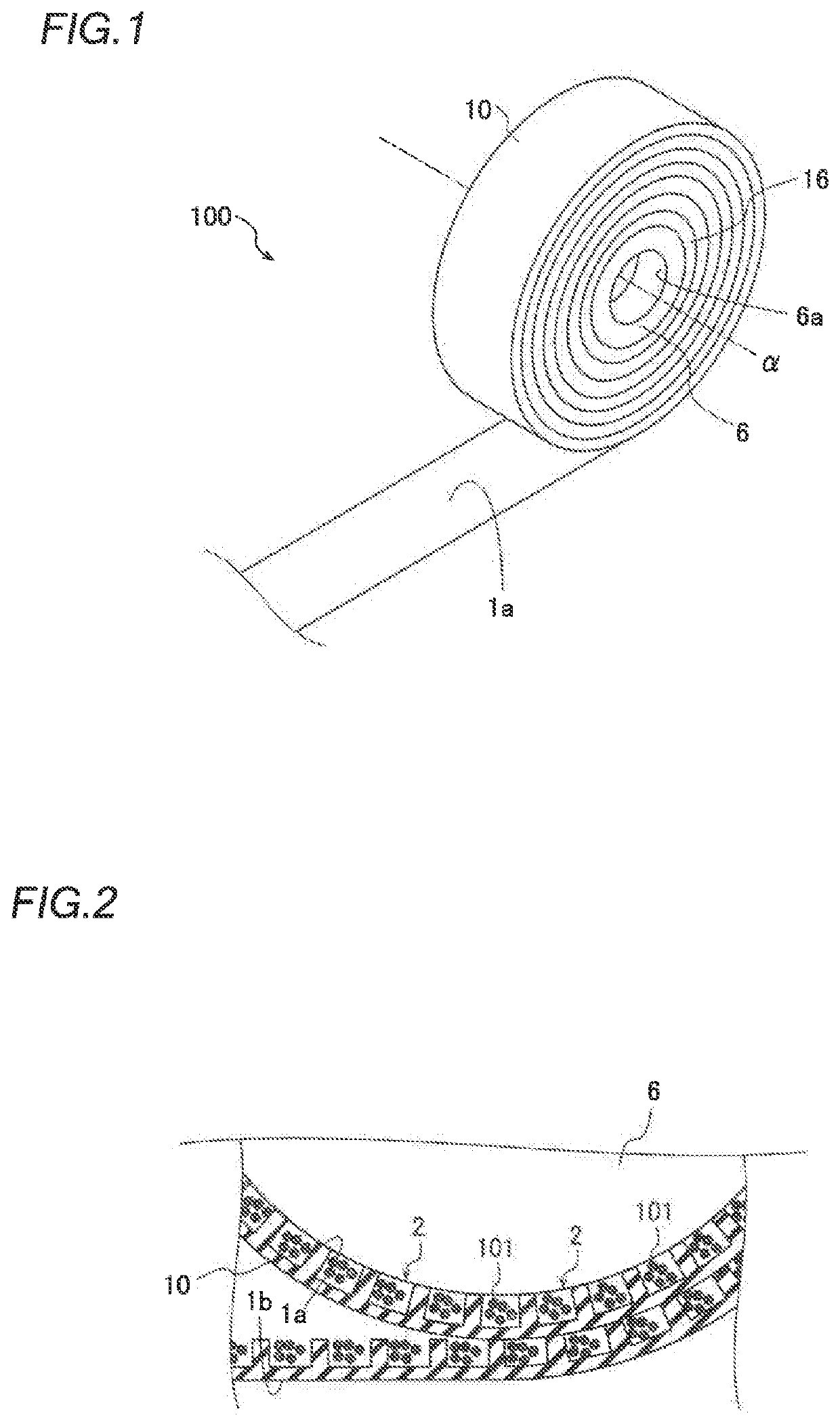
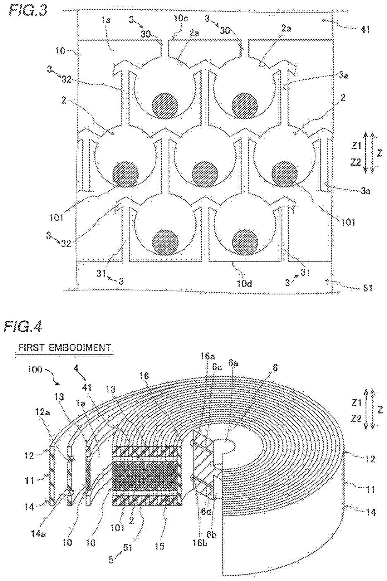
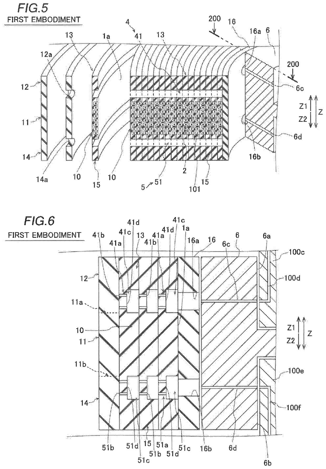
[0102]According to the first embodiment, as described above, the cell culture apparatus 100 includes the introduction port 40 into which the culture solution is introduced from the outside, and the introduction-side flow path 41 provided on the first side of the tape 10 in the direction in which the central axis α of the winding extends in a state in which the tape 10 is circumferential wound and through which the culture solution introduced from the outside flows and the introduced culture solution is introduced into each of the plurality of wells 2 of the tape 10 circumferentially wound. Furthermore, the cell culture apparatus 100 includes the tape-like seal 12 provided on the outer circumferential side of the introduction-side flow path 41 in a state in which the tape 10 is circumferentially wound and that blocks the flow of the culture solution from the introduction-side flow path ...

second embodiment

(Advantages Derived)

[0136]According to the second embodiment, the following advantages are obtained.

[0137]According to the second embodiment, as described above, in the cell culture apparatus 300, the introduction-side flow path 64b is surrounded by the introduction-side main body 61, the protrusion 62, the gasket 63, and the wound tape 20 in a state in which the gasket 63 provided on the protrusion 62 is in close contact with the blank tape 21. Accordingly, in a state in which the gasket 63 is in close contact with the blank tape 21, the protrusion 62 and the gasket 63 can significantly reduce or prevent leakage of the culture solution that flows through the introduction-side flow path 64b to the outer circumferential side. Furthermore, in a state in which the gasket 63 is in close contact with the blank tape 21, the introduction-side main body 61 can significantly reduce or prevent leakage of the culture solution that flows through the introduction-side flow path 64b from the firs...

third embodiment

(Advantages Derived)

[0171]According to the third embodiment, the following advantages are obtained.

[0172]According to the third embodiment, as described above, the core 46 includes the protruding end 46b provided on at least one end side of the core 46 in the direction in which the central axis α1 extends and that protrudes to the outside of the housing 80 through the opening 81a of the housing 80. Furthermore, the cell culture apparatus 400 includes the tube 90 connected to the flow path 46d of the protruding end 46b of the core 46 and through which the culture solution flows into the flow path 46d, and the tube 91 connected to the flow path 46e of the protruding end 46b of the core 46 and into which the culture solution flows from the flow path 46e. In addition, the cell culture apparatus 400 includes the annular O-ring 83 disposed adjacent to the opening 81a of the housing 80 and that circumferentially surrounds the core 46. When the tube 90 and the tube 91 are inserted into the ...


PUM

PropertyMeasurementUnit
flexibleaaaaaaaaaa
outer circumferenceaaaaaaaaaa
outer diameteraaaaaaaaaa

Abstract

A cell culture apparatus includes an introduction-side flow path arranged to allow a culture solution introduced to flow therethrough and be introduced therethrough into each of a plurality of concave wells of a flexible strip circumferentially wound, and a first introduction-side seal provided on an outer circumferential side of the introduction-side flow path, the first introduction-side seal being configured to block flow of the culture solution from the introduction-side flow path to an outer circumferential side of the flexible strip.

Description

CROSS-REFERENCE TO RELATED APPLICATIONS[0001]This application claims the benefit of priority to Japanese Patent Application No. 2018-110332 filed on Jun. 8, 2018. The entire contents of this application are hereby incorporated herein by reference.BACKGROUND OF THE INVENTIONField of the Invention[0002]The present invention relates to a cell culture apparatus, and more particularly, it relates to a cell culture apparatus that cultures cells on the circumferential surface of a circumferentially windable band.Description of the Background Art[0003]A cell culture apparatus that cultures cells on the circumferential surface of a circumferentially windable band is known in general. Such a cell culture apparatus is disclosed in U.S. Pat. Nos. 3,102,082, 3,853,712, 3,948,732, and 5,786,215, for example.[0004]In a cell culture apparatus disclosed in U.S. Pat. Nos. 3,102,082, 3,853,712, 3,948,732, and 5,786,215, cells are seeded on a surface of a circumferentially windable band. Specifically, ...

Claims


Application Information

Patent Timeline
Patent Type & Authority Applications(United States)
IPC IPC(8): C12M1/12C12M1/32C12M1/00C12M3/00
CPCC12M23/26C12M37/04C12M23/48C12M25/16C12M23/12C12M23/16C12M23/42C12M29/00
Inventor OHKUBO, TOMOKI
Owner SHIMADZU CORP
Why Eureka
Try Eureka