Flexible ring fitting device

a flexible ring and fitting technology, applied in metal-working equipment, vehicle components, metal-working equipment, etc., can solve the problems of not being able to respond to workpieces having various diameters, not being able to uniformly fit the o-ring into the workpiece groove, and not being able to fit the o-ring into the workpi

Active Publication Date: 2019-08-15
HONDA MOTOR CO LTD
View PDF0 Cites 0 Cited by
  • Summary
  • Abstract
  • Description
  • Claims
  • Application Information

AI Technical Summary

Benefits of technology

[0020]According to the present invention, it is possible to provide a flexible ring fitting device capable of fitting a flexible ring in response to workpieces having different diameters and capable of uniformly fitting an O-ring into a workpiece groove.

Problems solved by technology

Besides, even in a case where O-rings are fitted with respect to the workpieces having one type of diameter by means of the devices according to the related art described in Patent Documents 1 and 2, it is not easy to fit the O-ring into the workpiece groove without a positional relationship in which the axial center of the rotary shaft of the arm portion and the axial center of the workpiece coincide with each other.
Then, it is not easy to uniformly fit the O-ring into the workpiece groove.
Besides, in the device according to the related art, the O-ring can be fitted only into workpieces having one type of diameter that corresponds to the width of the rail, and thus it is impossible to respond to workpieces having various diameters.

Method used


Image

  • Flexible ring fitting device
  • Flexible ring fitting device
  • Flexible ring fitting device

Examples


Embodiment Construction

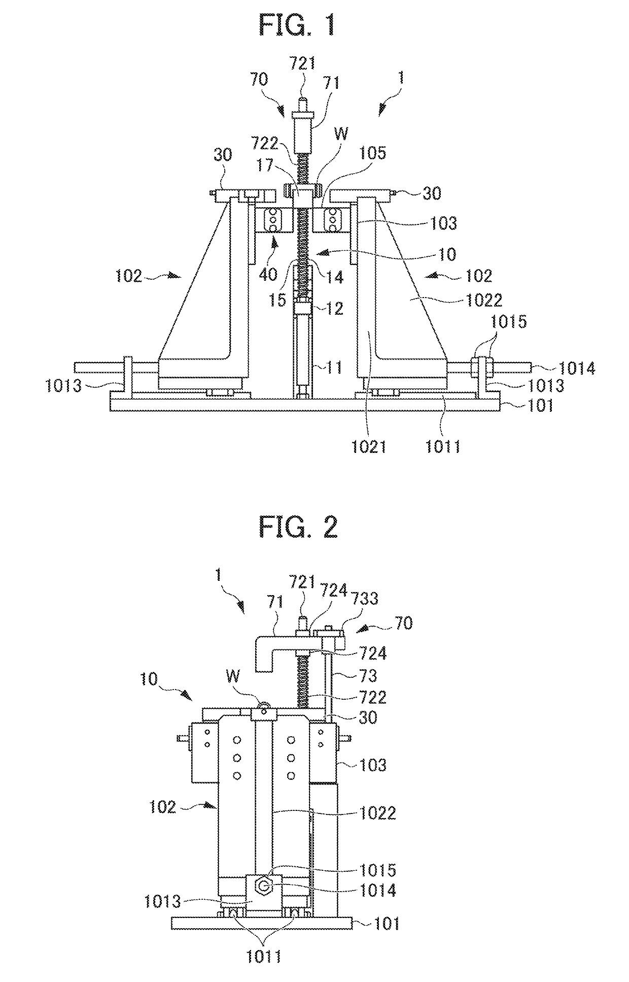
[0026]An embodiment of the present invention will be described in detail with reference to accompanying drawings. A flexible ring fitting device 1 is used so that a rubber-based O-ring R, which is a flexible ring, is fitted into a groove G (annular groove G). The groove G extends in the circumferential direction of a workpiece W and goes around. Each groove G is formed in the outer peripheral surface of a longitudinal end portion of the workpiece W. The workpiece W, which has a cylindrical shape, is a pipe member (pipe) interconnecting cases such as a crankcase and a differential case in a vehicle. FIG. 1 is a front view illustrating the flexible ring fitting device 1.

[0027]In the following description, the direction in which a pair of support side walls 102 (described later) is interconnected (leftward-rightward direction in FIG. 1) is defined as a leftward-rightward direction. In addition, the direction in which a first ring support member 411 (described later) is opened (directio...


PUM


Abstract

In a flexible ring fitting device 1, a flexible ring disposition mechanism includes at least two ring support members 411 and 412 disposed relative to each other and movable so as to be separated from each other. Notches 4113 and 4123 recessed in a direction in which the two ring support members 411 and 412 are separated from each other are formed along surfaces 4114 and 4124 of the two relative ring support members 411 and 412 in the relative surfaces 4114 and 4124 of the two ring support members 411 and 412. A flexible ring R is fitted into an annular groove G of a workpiece W by a workpiece disposition mechanism moving in one direction along with the workpiece W.

Description

[0001]This application is based on and claims the benefit of priority from Japanese Patent Application No. 2018-023516, filed on 13 Feb. 2018, the content of which is incorporated herein by reference.BACKGROUND OF THE INVENTIONField of the Invention[0002]The present invention relates to a flexible ring fitting device.Related Art[0003]Known in the related art are devices fitting a flexible O-ring into a groove of a columnar workpiece that has an outer peripheral surface where the groove (annular groove) is formed (see, for example, Patent Documents 1 and 2). In the devices, a rod-shaped member rotating along the outer peripheral surface of the workpiece is rotated while the O-ring is pressed against the workpiece. The O-ring is fitted into the groove of the workpiece as a result.[0004]Also known is a device provided with a holding mechanism for holding an O-ring in a direction perpendicular to a groove of a workpiece with the workpiece disposed such that the axial direction of the wo...

Claims


Application Information

Patent Timeline
Patent Type & Authority Applications(United States)
IPC IPC(8): B23P19/08
CPCB23P19/084B23P2700/50B23P19/006B25B27/28
Inventor FUKAZAWA, KINYA
Owner HONDA MOTOR CO LTD
Why Eureka
Try Eureka