Electronic module
a technology of electronic modules and connectors, applied in the field of electronic modules, can solve the problems of deteriorating reliability of electronic modules, difficult connection of control electrodes and connectors, and deteriorating controllability of electronic elements, so as to achieve stable disassembly, improve reliability, and suppress defective connections of second connectors
- Summary
- Abstract
- Description
- Claims
- Application Information
AI Technical Summary
Benefits of technology
Problems solved by technology
Method used
Image
Examples
first embodiment
>
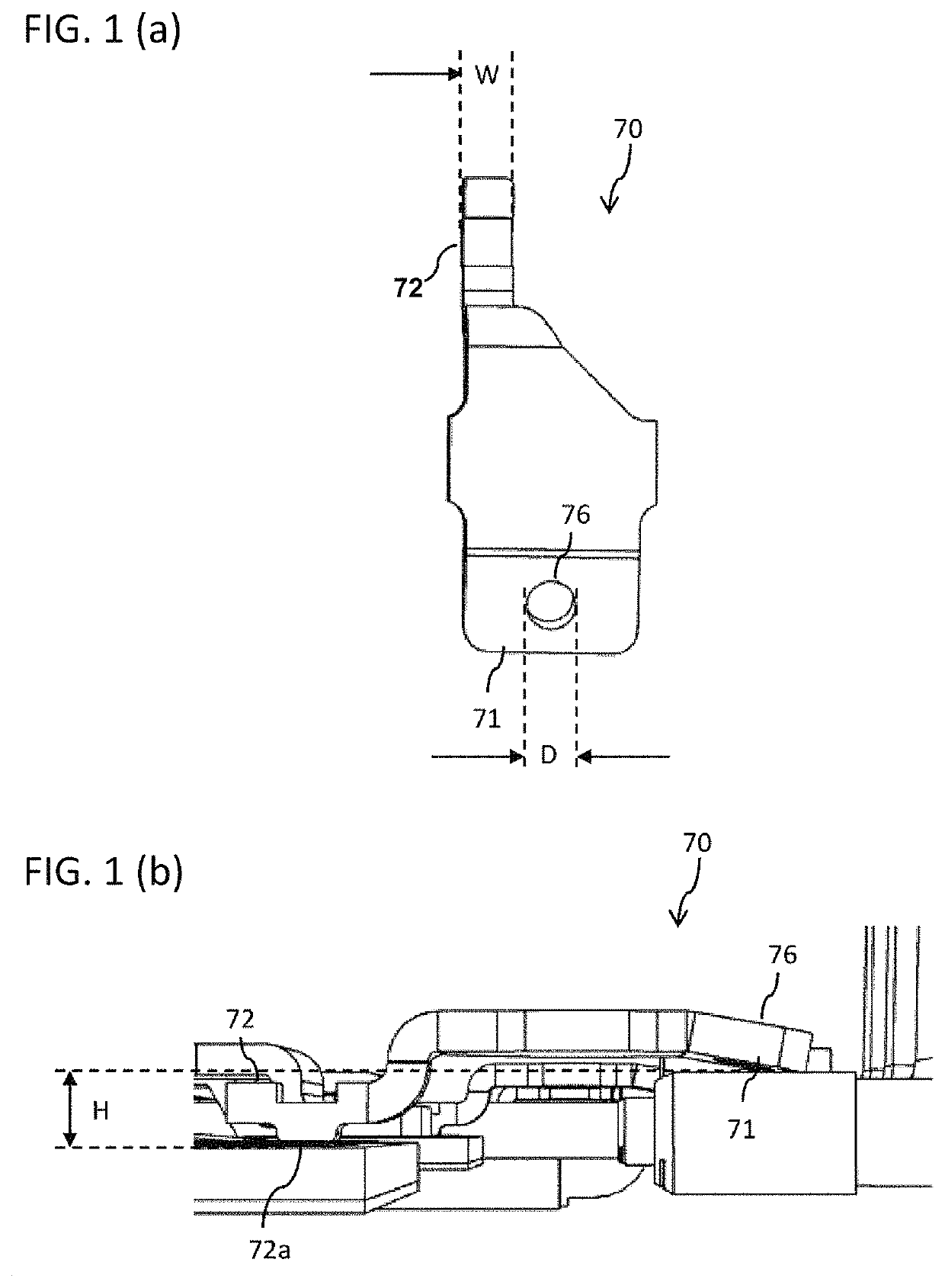
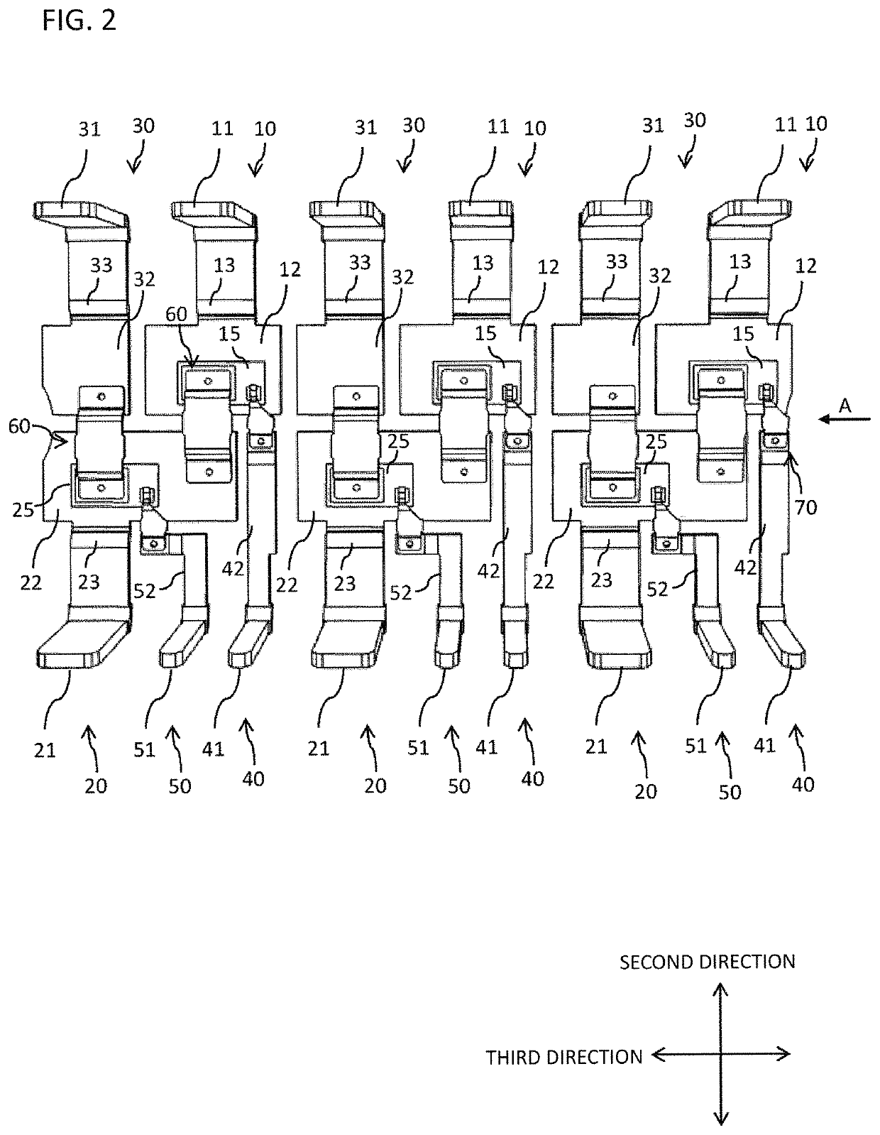
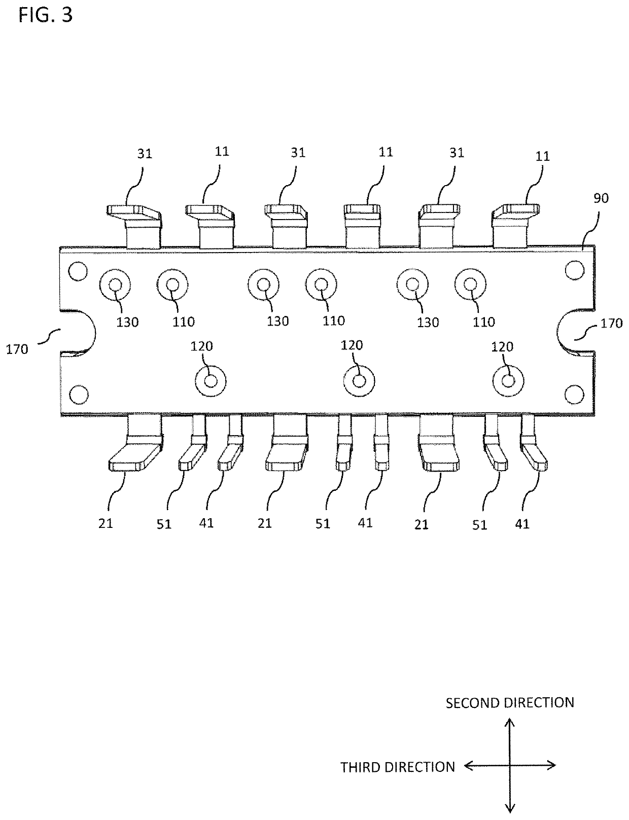
[0060]As illustrated in FIG. 2, an electronic module according to the present embodiment may have a sealing part 90 (refer to FIG. 3), rear surface-exposed conductors 10, 20 and 30, which have rear surface exposed-side terminal parts 11, 21 and 31 protruding outwardly from a side surface of the sealing part 90 and rear surface-exposed parts 12, 22 and 32 (refer to FIG. 8) whose rear surface is exposed, rear surface-unexposed conductors 40 and 50, which have rear surface unexposed-side terminal parts 41 and 51 protruding outwardly from a side surface of the sealing part 90 and whose rear surface is not exposed, a plurality of electronic elements 15 and 25, which is provided in the sealing part 90 and provided on a front surface of the rear surface-exposed conductors 10, 20, and 30 via a conductive adhesive 190 (refer to FIG. 11) such as solder, and connectors 60 and 70, which have a first connector 60 and a second connector 70. The connectors 60 and 70 have a first connector 60 and ...
second embodiment
[0115]Next, a second embodiment of the present invention will be described.
[0116]As indicated in FIG. 12, grooves 150 may be provided on the front surfaces of the rear surface-exposed parts 12, 22, and 32 of the rear surface-exposed conductors 10, 20, and 30. As indicated in FIG. 12, the groove 150 may be provided in each of the rear surface-exposed conductors 10, 20, and 30 or may be provided only in a part of the rear surface-exposed conductors 10, 20, and 30. As indicated in FIG. 13, in the longitudinal direction of the sealing part 90 in the in-plane direction, the center portion of the press holes or press impressions 110, 120, and 130 may be provided on the side opposite to the connectors 60 and 70 or the electronic elements 15 and 25 with respect to the groove 150. The groove 150 of the present embodiment does not penetrate through the rear surface-exposed parts 12, 22, and 32, and the recesses formed in the rear surface-exposed parts 12, 22, and 32 are the grooves 150. Howev...
third embodiment
[0128]Next, a third embodiment of the present invention will be described.
[0129]In the present embodiment, as illustrated in FIG. 14, the rear surface-exposed conductors 10, 20, and 30 are provided between the rear surface-exposed parts 12, 22, and 32 and the rear surface exposed-side terminal parts 11, 21 and 31, and the connected parts 16, 26 and 36 whose rear surface is not exposed are provided. More specifically, the connected parts 16, 26 and 36 whose rear surface is not exposed are provided between the internal bent parts 13, 23, and 33 and the rear surface-exposed parts 12, 22, and 32. The thickness of the connected parts 16, 26 and 36 is thinner than the thickness of the rear surface-exposed parts 12, 22, and 32 and the thickness of the rear surface exposed-side terminal parts 11, 21 and 31. For example, the thickness of the rear surface-exposed parts 12, 22, and 32 and the thickness of the rear surface exposed-side terminal parts 11, 21 and 31 are substantially the same, an...
PUM
 Abstract
Description
Claims
Application Information
 - R&D
- Intellectual Property
- Life Sciences
- Materials
- Tech Scout
- Unparalleled Data Quality
- Higher Quality Content
- 60% Fewer Hallucinations
Browse by: Latest US Patents, China's latest patents, Technical Efficacy Thesaurus, Application Domain, Technology Topic, Popular Technical Reports.
© 2025 PatSnap. All rights reserved.Legal|Privacy policy|Modern Slavery Act Transparency Statement|Sitemap|About US| Contact US: help@patsnap.com


