Rolling bearing and wind power generation rotor shaft support device

Active Publication Date: 2021-11-11
NTN CORP
View PDF0 Cites 0 Cited by
  • Summary
  • Abstract
  • Description
  • Claims
  • Application Information

AI Technical Summary

Benefits of technology

This patent describes a rolling bearing made of iron-based material with a hard film containing DLC and WC. The WC is a mixed layer that has both the hardness and elasticity of Cr and DLC, resulting in a residual stress that is low. The mixed layer also has a gradual composition of WC and DLC, which physically connects them together. The foundation layer formed on the inner and outer rings as well as the rolling contact surface is made of Cr, which makes it compatible with the iron-based material and has superior adhesiveness. The surface roughness of the bearing is small, resulting in high peeling resistance and reduced attackability to mating materials. The rolling bearing is therefore long-lasting and maintenance-free. The wind power generation rotor shaft support device uses this rolling bearing, which provides superior peeling resistance and resistance to seizure, wear, and corrosion. Overall, the present invention provides a unique solution for wind power generation that reduces damage to the bearing and improves its lifespan.

Problems solved by technology

Extremely large internal stress is generated when the DLC film is formed.
Although the DLC film has high hardness and high Young's modulus, the DLC film has extremely small deformability.
Thus, the DLC film has disadvantages that it is low in its adhesiveness to a base material and liable to peel therefrom.
Accordingly, when the bearing components are worn, wear debris is interposed between the rolling contact surfaces, which results in the damage of the raceway surface.

Method used


Image

  • Rolling bearing and wind power generation rotor shaft support device
  • Rolling bearing and wind power generation rotor shaft support device
  • Rolling bearing and wind power generation rotor shaft support device

Examples


examples

[0068]As the hard film used in the rolling bearing according to the present invention, the hard film was formed on a predetermined base material (specimen), and the properties of the hard film were evaluated. The wear of the mating material was evaluated by a rolling and sliding test using a two-cylinder test machine. These specimens are described below as examples and comparative examples.

[0069]The specimen, the UBMS apparatus, and the sputtering gas used for the evaluation of the hard films are as described below.

[0070](1) Specimen property: quenched and tempered SUJ2 of 750 Hv

[0071](2) Specimen: hard film is formed under each condition, on a sliding surface of a polished (the arithmetical mean roughness Ra, the root mean square gradient RΔq, the maximum peak height Rp, and the skewness Rsk are shown in Table 1) SUJ2 ring (ϕ40×L12, sub-curvature of 60)

[0072](3) UBMS apparatus: UBMS202 produced by Kobe Steel, Ltd.

[0073](4) Sputtering gas: Ar gas

[0074]The condition of forming the fo...


PUM


Abstract

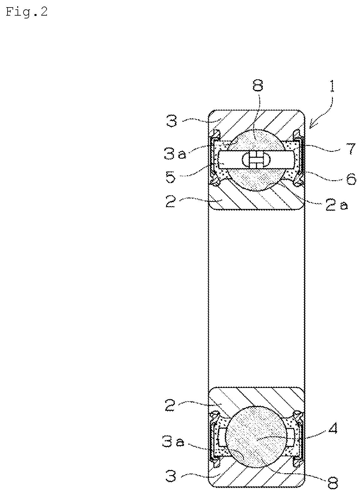
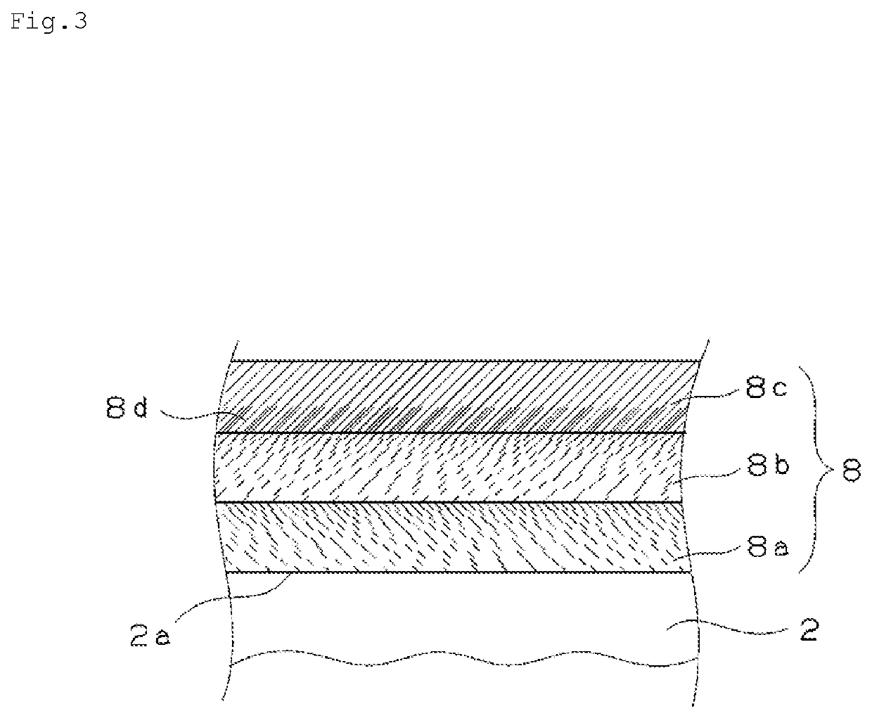
To provide a rolling bearing having a hard film on an inner ring raceway surface and an outer ring raceway surface of the rolling bearing that improves peeling resistance of the hard film, shows the original property of the hard film, and suppresses the attackability to a mating material. A rolling bearing 1 has an inner ring 2 having an inner ring raceway surface 2a on an outer circumference, an outer ring 3 having an outer ring raceway surface 3a on an inner circumference, and rolling elements 4 that roll between the inner ring raceway surface 2a and the outer ring raceway surface 3a. A hard film 8 includes a foundation layer formed directly on the inner ring raceway surface 2a or the outer ring raceway surface 3a and mainly formed of Cr and WC, a mixed layer having a gradient composition formed on the foundation layer and mainly formed of WC and DLC, and a surface layer formed on the mixed layer and mainly formed of DLC. In a roughness curve of a surface on which the foundation layer is formed, the arithmetical mean roughness Ra is 0.3 μm or less and the root mean square gradient RΔq is 0.05 or less.

Description

TECHNICAL FIELD[0001]The present invention relates to a rolling bearing in which a hard film including a diamond-like carbon is formed on a surface of an inner ring, an outer ring, and a rolling element, which are bearing components. In particular, the present invention relates to a double-row self-aligning roller bearing applied to a usage to which a high load is applied, for example a bearing that supports a rotor shaft of a wind power generator. Further, the present invention relates to a wind power generation rotor shaft support device having the double-row self-aligning roller bearing.BACKGROUND ART[0002]A hard carbon film is a hard film generally called diamond-like carbon (hereinafter, referred to as DLC. A film or a layer mainly formed of DLC is also called a DLC film or a DLC layer). Various names are given to the hard carbon. For example, it is called hard amorphous carbon, amorphous carbon, hard amorphous-type carbon, i-carbon, and diamond-shaped carbon. These terminologi...

Claims


Application Information

Patent Timeline
IPC IPC(8): F16C33/62F16C33/34F16C19/38F03D80/70
CPCF16C33/62F16C33/34F16C19/38F16C2206/04F16C2360/31F16C2206/82F03D80/70Y02E10/72C01B32/28C01B32/907F16C19/06F16C33/32F16C33/64Y02P20/133F16C33/585F16C23/086F16C2206/56F16C2240/56F16C33/6696F16C19/166
Inventor NAKANISHI, MASAKIMIKAMI, HIDENOBU
Owner NTN CORP
Why Eureka
Try Eureka